
Earth and Atmospheric Sciences

Alternating Current (AC) circuits are electrical circuits in which the flow of electric charge periodically reverses direction. Unlike Direct Current (DC), where electrons flow steadily in one direction (like a battery), AC mimics a wave-like motion, constantly pushing and pulling energy through the conductor.
Circuit Construction Kit: AC – PhET
This technology is the standard for power distribution worldwide because it can be easily stepped up to high voltages for long-distance transmission and then stepped down for safe home use.

1. The Sine Wave
In an AC circuit, the voltage and current vary according to a sine wave function. This means the intensity of the current starts at zero, rises to a maximum positive peak, returns to zero, drops to a maximum negative peak, and then returns to zero again to complete one cycle.
- Frequency (f): The number of cycles completed per second, measured in Hertz (Hz). In North America, the standard is 60 Hz, while much of the rest of the world uses 50 Hz.
- Amplitude: The maximum value (peak) reached by the voltage or current.
2. Key Components in AC Circuits
While DC circuits primarily deal with resistance, AC circuits are influenced by three main properties:
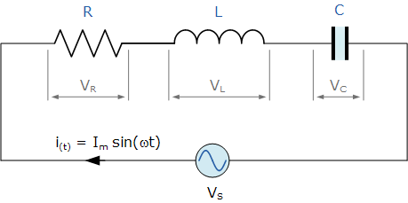
- Resistance (R): Opposes the flow of current and converts electrical energy into heat. In a purely resistive circuit, voltage and current are “in phase” (they peak at the same time).
- Inductance (L): Found in components like coils and motors. Inductors store energy in a magnetic field and cause the current to “lag” behind the voltage.
- Capacitance (C): Found in capacitors, which store energy in an electric field. Capacitors cause the current to “lead” the voltage.
3. Impedance and Phasors
Because of the timing differences caused by inductors and capacitors, calculating total opposition to current isn’t as simple as adding numbers. This total opposition is called Impedance (Z).
To analyze these circuits, engineers use Phasors—rotating vectors that represent the amplitude and phase of the AC signals. The relationship is expressed using complex numbers:
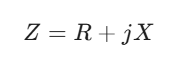
Where:
- Z is the Impedance (measured in Ohms, Ω).
- R is the Resistance.
- X is the Reactance (the combined effect of inductance and capacitance).
- j is the imaginary unit (used to represent the 90-degree phase shift).
4. Real-World Application: Power Factor
In a perfect world, the voltage and current would peak simultaneously. However, because most industrial equipment uses motors (inductors), the current often lags behind. This creates “reactive power,” which does no work but still occupies space in the power lines. Power Factor is the ratio of actual power used to the total power supplied; a higher power factor indicates a more efficient system.
What is the relationship between capacitors and capacitive resistance?
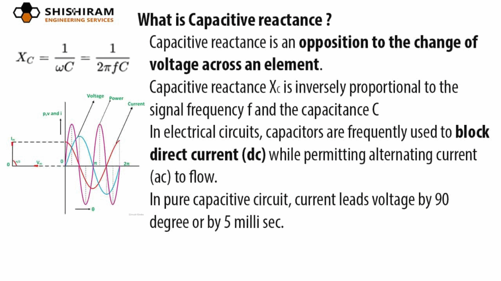
In an alternating current (AC) circuit, a capacitor does not provide a simple resistance like a toaster or a lightbulb. Instead, it offers Capacitive Reactance (XC), which is a form of opposition to the flow of current that depends on both the physical properties of the capacitor and the frequency of the electrical signal.
The relationship between a capacitor’s physical ability to store charge (Capacitance) and its opposition to current (Reactance) is inversely proportional.
1. The Mathematical Relationship
The formula for capacitive reactance (XC) is defined as:
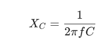
Where:
- XC is the Capacitive Reactance, measured in Ohms (Ω).
- f is the Frequency of the AC signal, measured in Hertz (Hz).
- C is the Capacitance, measured in Farads (F).
- π represents the constant for a full cycle (angular velocity).

2. How Capacitance Affects Reactance
Capacitance is the measure of how much electrical energy a component can store.
- Higher Capacitance: A “larger” capacitor can hold more charge. Because it takes longer to fill up, it allows more current to flow through the circuit before it pushes back, resulting in lower reactance (less opposition).
- Lower Capacitance: A “smaller” capacitor fills up almost instantly. Once full, it stops the flow of current, resulting in higher reactance (more opposition).
3. The Role of Frequency
The most unique aspect of this relationship is that it changes based on how fast the current reverses direction:
- High Frequency: The current changes direction so fast that the capacitor never has time to fully charge. It acts almost like a short circuit, offering very low reactance.
- Low Frequency: The capacitor has plenty of time to charge up and block the flow. This creates high reactance.
- Direct Current (DC): In DC, the frequency is zero (f = 0). If you look at the formula, dividing by zero makes the reactance infinite. This is why capacitors block DC entirely once they are charged.
4. Phase Shift: Current Leads Voltage
In a purely capacitive circuit, the capacitor resists changes in voltage. Because the capacitor must charge up before the voltage can rise across its plates, the current (I) actually reaches its peak before the voltage (V).
This is known as a 90° phase lead. In technical terms, we say the current “leads” the voltage by 90 degrees.
What is the relationship between inductance and inductive resistance?
In an alternating current (AC) circuit, an inductor (typically a coil of wire) opposes changes in current by storing energy in a magnetic field. This opposition is called Inductive Reactance (XL), and it is directly proportional to both the physical properties of the inductor and the frequency of the AC signal.
Unlike a capacitor, which opposes voltage, an inductor opposes the rate of change of current.
1. The Mathematical Relationship
The formula for inductive reactance (XL) is:
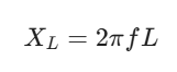
Where:
- XL is the Inductive Reactance, measured in Ohms (Ω).
- f is the Frequency of the AC signal, measured in Hertz (Hz).
- L is the Inductance, measured in Henries (H).
- 2π represents the angular frequency (Ω).
2. How Inductance Affects Reactance
Inductance is a measure of how effectively a coil creates a magnetic field to oppose current changes.
- Higher Inductance (L): A larger coil or one with a magnetic core creates a stronger magnetic field. This creates a stronger “back EMF” (electromotive force) that fights the incoming current, resulting in higher reactance.
- Lower Inductance (L): A smaller coil with fewer turns creates a weaker field, offering lower reactance.

3. The Role of Frequency
Because an inductor reacts to how fast the current is changing, frequency plays a critical role:
- High Frequency: The current is trying to change direction very rapidly. The inductor fights these rapid changes aggressively, leading to very high reactance. At extremely high frequencies, an inductor can act like an open circuit.
- Low Frequency: The current changes slowly, giving the magnetic field time to stabilize. This results in low reactance.
- Direct Current (DC): In DC, the frequency is zero (f = 0). Plugging this into the formula gives a reactance of zero. Therefore, once the initial magnetic field is established, an inductor acts like a simple wire (short circuit) in a DC circuit.
4. Phase Shift: Voltage Leads Current
In a purely inductive circuit, the inductor’s “back EMF” immediately opposes any incoming current. Because the voltage must be applied to overcome this opposition before the current can start to flow, the voltage (V) reaches its peak before the current (I).
This results in a 90° phase lag for the current. Engineers often use the mnemonic ELI the ICE man:
- E (Voltage) leads I (Current) in an L (Inductor).
- I (Current) leads E (Voltage) in a C (Capacitor).
How are circuits containing resistance, capacitance, and inductance represented?
When a circuit contains all three elements—Resistance (R), Inductance (L), and Capacitance (C)—it is known as an RLC circuit. These circuits are unique because the different components interact with the alternating current in opposing ways.
The behavior of an RLC circuit depends on whether the components are arranged in series (one after another) or in parallel (side-by-side).
1. The Conflict of Phase
In an RLC circuit, each component handles the timing of the current differently:
- Resistors keep voltage and current in sync.
- Inductors make the current lag behind (ELI).
- Capacitors make the current lead ahead (ICE).
Because inductors and capacitors have opposite effects on the phase, they actually work against each other. This “tug-of-war” determines the overall behavior of the circuit.
Play retro 1943 game Online – Arcade, Nintendo, Atari and Sega Games
2. Total Impedance (Z)
You cannot simply add the Ohms of a resistor, an inductor, and a capacitor together. Instead, you must use vector addition (or complex numbers) to find the Total Impedance.
For a series RLC circuit, the formula is:
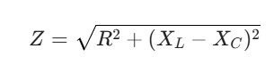
Where:
- R is the Resistance.
- XL is the Inductive Reactance (2πfL).
- XC is the Capacitive Reactance (1 / (2πfC)).
Notice the (XL – XC) term: this shows that inductance and capacitance subtract from one another. The circuit will behave more like an inductor or more like a capacitor depending on which reactance is larger.
3. Resonance: The Sweet Spot
There is a specific frequency where XL exactly equals XC. When this happens, they cancel each other out entirely (XL – XC = 0). This state is called Resonance.
- At Resonance: The total impedance is at its absolute minimum (equal only to the resistance $R$).
- Result: Current flow is at its maximum.
- Applications: This is how radio tuners work. By adjusting the capacitance or inductance, you change the resonant frequency of the circuit to “catch” a specific broadcast frequency while blocking others.
4. Summary of Circuit Types
| Circuit Condition | Behavior | Phase Relationship |
| XL > XC | Inductive | Current lags voltage (Lagging Power Factor) |
| XC > XL | Capacitive | Current leads voltage (Leading Power Factor) |
| XL = XC | Resonant | Voltage and current are in phase (Unity Power Factor) |
What is resonance in electric circuits?
In electric circuits, resonance is a specific state that occurs when the inductive reactance (XL) and capacitive reactance (XC) are equal in magnitude but opposite in phase. At this precise frequency, they effectively cancel each other out, leaving only the resistance (R) to oppose the flow of current.
Think of it like a playground swing: if you push at just the right timing (the resonant frequency), the amplitude of the motion increases significantly with very little effort.
1. The Resonant Frequency (fr)

Every circuit containing both an inductor and a capacitor has a natural “ringing” frequency. This frequency is determined by the values of the components.
The formula to find the resonant frequency is:
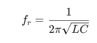
At this frequency, the energy oscillates back and forth between the magnetic field of the inductor and the electric field of the capacitor with maximum efficiency.
2. Series vs. Parallel Resonance
Resonance behaves differently depending on how the components are arranged:
Series Resonance
In a series RLC circuit, the total impedance ($Z$) is at its minimum during resonance.
- Impedance: Z = R (because XL and XC cancel).
- Current: Reaches its maximum value.
- Usage: Used in radio receivers to “tune in” to a specific station by allowing only that frequency to pass through with high current.
Parallel Resonance
In a parallel RLC circuit, the opposite happens. The total impedance is at its maximum during resonance.
- Impedance: Reaches a peak (theoretically infinite if there were no resistance).
- Current: The external line current is at its minimum.
- Usage: Used as “rejector” circuits or filters to block a specific unwanted frequency while letting others pass.

3. The “Q” Factor (Quality Factor)
The “sharpness” of the resonance is measured by the Q factor.
- High Q: The circuit is very selective; it responds strongly to a very narrow range of frequencies. This is ideal for high-quality radio tuning.
- Low Q: The circuit has a “flat” response and reacts to a broader range of frequencies. This is often caused by having higher resistance in the circuit.
4. Real-World Applications
Resonance is a fundamental principle in modern technology:
- Communications: Tuning your TV or radio to a specific channel.
- Filters: Removing “noise” from audio or power signals.
- Wireless Charging: Matching the resonant frequency of a charging pad and a phone to transfer power efficiently through the air.
- Metal Detectors: Sensing the change in resonance when a metal object enters the magnetic field of a coil.
What are semiconductor devices?
Semiconductor devices are electronic components that exploit the unique electrical properties of semiconductor materials—primarily Silicon and Germanium.
These materials are called “semiconductors” because their ability to conduct electricity sits between a conductor (like copper) and an insulator (like glass). By adding small amounts of impurities—a process called doping—engineers can precisely control how and when these materials allow current to flow.
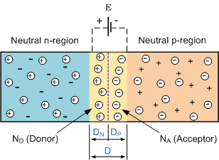
1. The Building Blocks: P-Type and N-Type
To create a device, semiconductors are doped to create two distinct types of material:
- N-Type (Negative): Infused with elements that provide extra electrons.
- P-Type (Positive): Infused with elements that create “holes” (the absence of an electron, which acts as a positive charge carrier).
When these two materials are joined, they form a P-N Junction, which is the “beating heart” of almost all semiconductor technology.
2. Common Semiconductor Devices
Semiconductor devices are generally categorized into two groups based on their complexity:
Two-Terminal Devices (Diodes)
A Diode is the simplest semiconductor device. It acts as a “one-way valve” for electricity.
- Function: It allows current to flow in one direction but blocks it in the opposite direction.
- Applications: Converting AC to DC (rectification), protecting circuits from battery reversal, and LEDs (Light Emitting Diodes).
Three-Terminal Devices (Transistors)
The Transistor is the most important invention of the 20th century. It acts as either a switch or an amplifier.
- Bipolar Junction Transistor (BJT): Uses a small input current to control a larger output current.
- Field-Effect Transistor (MOSFET): Uses a voltage (electric field) to control current flow. These are the microscopic switches found by the billions inside computer processors.
3. Integrated Circuits (The “Chip”)
An Integrated Circuit (IC) isn’t a single device, but a collection of thousands or billions of microscopic transistors, diodes, and resistors etched onto a single small plate (wafer) of silicon.

These “chips” handle everything from simple timing in a microwave to the complex processing required for Artificial Intelligence.
4. Why Semiconductors Changed the World
Before semiconductors, electronic devices relied on Vacuum Tubes, which were bulky, fragile, produced immense heat, and frequently burned out. Semiconductors offered:
- Miniaturization: Millions of components can fit in a space smaller than a fingernail.
- Efficiency: They require very little power to operate.
- Reliability: Since they have no moving parts or filaments to burn out, they can last for decades.
5. Summary Table
| Device | Main Function | Analogy |
| Diode | One-way current flow | Check Valve |
| Transistor | Switching or Amplifying | Water Faucet |
| LED | Converts electricity to light | Glowing Valve |
| Photodiode | Converts light to electricity | Light-Sensitive Switch |