
What is the relationship between information technology hardware and software
Information Technology Systems
At its core, Information Technology (IT) configuration is the process of setting up and maintaining the specific settings, properties, and relationships of all components within a technical environment. It ensures that hardware, software, and network systems work together predictably and reliably.
Play original Arkanoid Online – Arcade, Nintendo, Atari and Sega Games
Think of it as the “DNA” of an IT system—it defines exactly how a computer, server, or application is supposed to behave.
Key Components of Configuration
Configuration isn’t just one task; it covers several layers of an organization’s infrastructure:
- Hardware Configuration: Setting up physical devices, such as assigning IP addresses to routers, allocating RAM to virtual machines, or defining BIOS settings.
- Software Configuration: Managing application settings, such as registry keys, installation paths, user permissions, and versioning.
- Network Configuration: Establishing the rules for communication, including firewall settings, DNS records, and VPN tunnels.
The Concept of a “Configuration Item” (CI)
In professional IT management (specifically within the ITIL framework), any component that needs to be managed to deliver an IT service is called a Configuration Item (CI). These can be:
- Physical: Servers, laptops, or cabling.
- Logical: Software licenses, documentation, or service-level agreements (SLAs).
- Relational: How a specific database connects to a web server.
Why Configuration Management Matters
Without a disciplined approach to configuration, systems fall into “Configuration Drift.” This happens when small, undocumented changes occur over time, making it impossible to troubleshoot issues because the “current” state of the system no longer matches the “intended” state.
1. Consistency and Security
Standardized configurations ensure that every laptop in a company has the same security patches and firewall rules, reducing the “attack surface” for hackers.
2. Disaster Recovery
If a server fails, having a precise record of its configuration allows IT teams to rebuild it exactly as it was, rather than guessing at settings and permissions.
3. Automation (Infrastructure as Code)
Modern IT often uses Infrastructure as Code (IaC). Instead of manually clicking through menus, specialists write scripts (using tools like Ansible or Terraform) that automatically apply configurations to thousands of devices simultaneously.
Configuration vs. Customization
It is helpful to distinguish between these two frequently confused terms:
- Configuration: Using the built-in tools and “switches” provided by a vendor to make a system work (e.g., turning on “Dark Mode” in an app).
- Customization: Changing the underlying code or adding new features that weren’t originally there (e.g., writing a new plugin to change how an app functions).
What is IT software configuration?
At its most practical level, IT software configuration is the process of defining and managing the specific settings, parameters, and environmental variables that determine how a software application behaves and interacts with its ecosystem.
While “installing” software puts the files on a drive, “configuring” it is what makes it functional, secure, and tailored to a specific purpose.
Core Elements of Software Configuration
Play Ms Pac-Man Online – Arcade, Nintendo and Atari free Game play
Software isn’t a static box; it relies on a variety of external instructions to run correctly. These instructions typically fall into several categories:
1. Environmental Variables
These tell the software about the “room” it is living in. This includes:
- Pathing: Where to find dependent libraries or temporary folders.
- Connections: Database strings (IP addresses, ports) and API keys.
- Operating Mode: Switching between “Development,” “Testing,” or “Production” environments.
2. User & Access Permissions
Configuration defines who can do what. This involves setting up:
- Role-Based Access Control (RBAC).
- Integration with identity providers (like Active Directory or Google Workspace).
- Encryption standards for data at rest and in transit.
3. Feature Flags & Preferences
Many modern applications use “feature flags” to turn specific functionalities on or off without changing the underlying code. Configuration manages:
- UI preferences (language, time zones, themes).
- Performance throttles (limiting how much CPU or memory the app can use).
- Functional toggles (enabling a new “Beta” checkout button for only 10% of users).
The Concept of “Stateless” vs. “Stateful” Configuration
In modern IT infrastructure, we often distinguish between how configuration is stored:
- Config Files: Traditional settings stored in
.ini,.xml,.json, or.yamlfiles located on the same server as the software. - Externalized Config: Storing settings in a central “Vault” or “Config Server.” This allows a fleet of 100 servers to all pull the same settings simultaneously, ensuring consistency across a global network.
Configuration Management (SCM)
To prevent “Configuration Drift”—where settings are manually changed and forgotten—IT professionals use Software Configuration Management (SCM). This involves:
- Version Control: Keeping every version of a configuration file in a repository (like Git) so you can “roll back” if a change breaks the system.
- Baselines: Establishing a “known good” state that the software must always return to.
- Auditing: Automatically checking if a setting has been changed unauthorizedly and “remediating” it back to the standard.
Configuration vs. Hard-Coding
A primary rule in professional software deployment is “Never hard-code configuration.”
- Hard-coding: Writing a database password directly into the source code. If the password changes, you have to rewrite and recompile the entire program.
- Configuration: Placing that password in a secure, external configuration file. If the password changes, you simply update the file, and the software picks up the change instantly.
What is BIOS?
At its most fundamental level, BIOS stands for Basic Input/Output System. It is the first piece of software that runs when you turn on a computer, acting as the critical bridge between your computer’s hardware and its operating system (like Windows, Linux, or macOS).
Without BIOS, your computer would be a collection of expensive metal and silicon that doesn’t know how to “talk” to itself or start up.
What Does BIOS Actually Do?
The BIOS follows a specific sequence every time you press the power button, often referred to as the Boot Process:
- POST (Power-On Self-Test): This is a diagnostic “health check.” The BIOS tests your hardware—checking if the RAM is functional, if the CPU is overheating, and if the keyboard and mouse are connected. If something is wrong, you might hear a series of “beeps” (beep codes).
- Hardware Initialization: Once the hardware passes the test, BIOS assigns resources and identifies all connected devices, such as hard drives, SSDs, and optical drives.
- Bootstrap Loader: The BIOS looks for an “executable” operating system on a storage device. It follows a specific Boot Order (e.g., check the USB drive first, then the primary SSD).
- Handoff: Once it finds the OS, it hands over control of the hardware to the operating system, and the BIOS goes into a background state.
Where is BIOS Located?
Unlike your operating system or your photos, BIOS is not stored on your hard drive. It is stored on a non-volatile ROM (Read-Only Memory) chip located directly on the motherboard.
- Non-volatile means it doesn’t disappear when you turn the power off.
- Historically, this chip used a small CMOS battery (which looks like a watch battery) to keep the system clock accurate and remember custom settings even when the PC was unplugged.
BIOS vs. UEFI: The Modern Standard
If you have bought a computer in the last decade, you likely aren’t using a “traditional” BIOS. You are using UEFI (Unified Extensible Firmware Interface).
While people still call it “the BIOS” out of habit, UEFI is the modern successor. The differences are significant:
| Feature | Legacy BIOS | Modern UEFI |
| Interface | Text-only (Blue/Grey screen) | Graphical (Supports Mouse & Icons) |
| Drive Size | Limited to 2.2 TB | Supports up to 9 Zettabytes |
| Boot Speed | Slower initialization | “Fast Boot” capabilities |
| Security | Minimal | Secure Boot (prevents malware at startup) |
Accessing and Configuring BIOS
Users typically enter the BIOS/UEFI menu to change low-level hardware settings. This is done by tapping a specific key (usually F2, F12, or Delete) the moment the computer starts.
Common reasons to enter BIOS configuration include:
- Changing the Boot Priority (e.g., booting from a USB to install a new OS).
- Adjusting Fan Speeds or monitoring CPU temperature.
- Enabling Virtualization (VT-x or AMD-V) for running virtual machines.
- Overclocking the CPU or RAM for higher performance.
What is the setup program?
In the context of computer hardware and IT infrastructure, the Setup Program (often called the BIOS Setup Utility or UEFI Settings) is the built-in interface used to configure a computer’s most basic hardware settings before the operating system even loads.
It is stored on a small memory chip on the motherboard, separate from your hard drive or SSD.
What the Setup Program Controls
When you enter the setup program, you are communicating directly with the motherboard firmware. Key configurable areas include:
- Boot Priority: Deciding which drive the computer checks first for an operating system (e.g., forcing it to boot from a USB drive instead of the internal SSD).
- Clock and Date: Setting the System Time, which is maintained by the CMOS battery even when the computer is unplugged.
- Hardware Monitoring: Viewing real-time data like CPU temperature, fan speeds, and voltage levels.
- Power Management: Configuring how the computer wakes up (e.g., “Wake-on-LAN”) or how it behaves after a power failure.
- Security Settings: Setting a “Supervisor Password” to prevent unauthorized users from changing hardware settings or enabling Secure Boot to prevent untrusted software from loading during startup.
Entering the Setup Program
Because the setup program runs before Windows or macOS, you cannot open it like a regular app. Instead, you must trigger it during the POST (Power-On Self-Test) phase:
- Restart the computer.
- Tap a specific key repeatedly as soon as the logo appears (usually F2, F10, Delete, or Esc).
- On modern UEFI systems, you can also reach it through Windows “Advanced Startup” options if the “Fast Boot” setting makes the timing too difficult to catch manually.
BIOS Setup vs. OS Settings
It is important to distinguish the Setup Program from the settings you find inside your operating system (like the Windows Settings app or Control Panel):
| Feature | BIOS/UEFI Setup Program | Operating System Settings |
| Availability | Before the OS loads | After the OS loads |
| Storage Location | Motherboard Firmware Chip | Hard Drive / SSD |
| Primary Focus | Physical hardware & boot logic | User interface, apps, & drivers |
| Risk Level | High (Incorrect settings can prevent booting) | Moderate (Usually recoverable) |
When Should You Use It?
Most users never need to enter the setup program. However, it is essential for:
- Upgrading Hardware: Ensuring the motherboard recognizes a new CPU or higher-speed RAM (often involving XMP or DOCP profiles).
- System Troubleshooting: If a computer isn’t “seeing” a hard drive, the setup program can confirm if the hardware is physically detected.
- Virtualization: Enabling settings like Intel VT-x or AMD-V, which are required to run virtual machines or certain high-performance emulators.
What is flash BIOS?
Flash BIOS is both a verb and a noun in the IT world. As a noun, it refers to a BIOS stored on Flash memory (a type of non-volatile storage that can be electronically erased and rewritten). As a verb, “flashing” is the process of updating that firmware to a newer version.
In older computers, BIOS was stored on ROM chips that were permanent or required UV light to erase. Modern Flash BIOS allows you to update your motherboard’s “brain” using a simple software utility.
Why Would You “Flash” the BIOS?
Because the BIOS/UEFI controls the communication between hardware and software, you typically only flash it for specific, high-priority reasons:
- Hardware Compatibility: If you buy a brand-new CPU that was released after your motherboard was manufactured, the motherboard might not “know” how to talk to it. A BIOS flash provides the necessary microcode to support the new chip.
- Fixing Bugs: Manufacturers release updates to fix stability issues, such as random system crashes or “Blue Screens of Death” caused by hardware timing errors.
- Security Patches: Firmware-level vulnerabilities (like those that target the boot process) are patched through BIOS updates.
- Performance Tweak: Updates can improve RAM compatibility or add support for faster data transfer protocols (like Resizable BAR for GPUs).
How the Process Works
Updating the BIOS is different from updating a standard app or your operating system. It usually follows one of these three paths:
- UEFI Instant Flash: You place the update file on a USB drive, enter the Setup Program (BIOS menu), and select the “Flash” utility built into the firmware.
- Internet Update: Some modern motherboards can connect directly to the manufacturer’s servers while inside the UEFI menu to download and install the update.
- BIOS Flashback: A high-end feature where you can update the BIOS using a dedicated USB port and button on the back of the PC, even if there is no CPU or RAM installed.
The “Golden Rule” of Flashing BIOS
If it isn’t broken, don’t fix it. Unlike Windows updates, which you should almost always install, a BIOS flash carries a small but significant risk. If the power goes out or the computer freezes during the 2–3 minutes it takes to rewrite the chip, the BIOS can become corrupted. This results in a “Bricked” motherboard, meaning the computer will no longer turn on because it has lost its basic instructions for booting.
Pro Tip: Always ensure your computer is plugged into a stable power source (or a UPS battery backup) before starting a flash.
Flash BIOS vs. CMOS Reset
It is common to confuse “flashing” with “resetting.”
- CMOS Reset: Simply wipes your custom settings (like your clock or boot order) and returns them to factory defaults. It does not change the BIOS version.
- Flash BIOS: Replaces the entire operating program of the motherboard with a newer version.
What are the BIOS/UEFI configuration settings?
When you enter the Setup Program (BIOS or UEFI), you are looking at the “Master Control Panel” for your computer’s hardware. While every motherboard manufacturer (ASUS, MSI, Gigabyte, Dell, etc.) has a slightly different layout, the settings are generally grouped into several core categories.
1. Main / System Information
This is the landing page. It is mostly “read-only” and provides a snapshot of what the computer detects.
- System Time/Date: Essential for security certificates in your browser to work correctly.
- Processor Details: Shows the CPU model, core count, and current frequency.
- Memory Summary: Lists how much RAM is installed and what slots are being used.
- BIOS Version: Critical for knowing if you need to “Flash” the BIOS for newer hardware support.
2. Boot Settings
This is the most frequently visited section. It determines how the computer starts up.
- Boot Priority / Order: A list of devices (SSD, Hard Drive, USB, Network). If you want to install a new OS from a thumb drive, you move “USB Device” to the #1 spot.
- Fast Boot: Skips certain hardware checks during startup to reach the Windows login screen faster.
- Secure Boot: (UEFI only) Ensures that only “trusted” software (like Windows or verified Linux) can load, preventing rootkit malware from hijacking the boot process.
- Compatibility Support Module (CSM): Allows a modern UEFI system to act like an old “Legacy” BIOS for older operating systems.
3. Advanced / Peripheral Configuration
This section controls the individual “limbs” of the motherboard.
- SATA / NVMe Configuration: Switches between AHCI (standard) and RAID (combining multiple drives).
- Onboard Devices: Allows you to disable hardware you aren’t using, like the onboard Wi-Fi, Audio chip, or Ethernet port.
- USB Configuration: Controls whether USB ports are active during boot or only after the OS loads.
- Virtualization (VT-x / AMD-V): Must be enabled if you plan to use virtual machines (VirtualBox, VMware) or the Windows Subsystem for Linux (WSL).
4. Overclocking / Performance (Often labeled “AI Tweaker” or “OC”)
Note: These settings can be dangerous if misconfigured.
- XMP / DOCP / EXPO: One-click settings that tell your RAM to run at its advertised high speed rather than the basic “safe” speed.
- CPU Ratio / Multiplier: Increases the clock speed of the processor for more power.
- Voltage Control: Manages the electricity sent to components. Too much can fry hardware; too little causes crashes.
5. Security Settings
- Administrator/Supervisor Password: Prevents anyone from changing BIOS settings without a code.
- User Password: Requires a password before the computer even attempts to load the operating system.
- TPM (Trusted Platform Module): Must be enabled for features like Windows BitLocker encryption or Windows 11 compatibility.
6. Power & Monitoring
- Fan Control (Q-Fan / Smart Fan): Allows you to set “Fan Curves” so your PC stays quiet when idle but ramps up the cooling during heavy tasks.
- Hardware Monitor: Displays real-time temperatures and voltages to ensure nothing is overheating.
- Restore on AC Power Loss: Determines if the PC stays off or automatically turns back on if the power blips.
Summary Table: Common Configuration Tasks
| If you want to… | Look for this setting: |
| Install Windows from a USB | Boot Priority / Boot Order |
| Run a Virtual Machine | Intel VT-x or AMD-V (Virtualization) |
| Make RAM run at rated speed | XMP / DOCP Profile |
| Check if a drive is broken | Storage / SATA Configuration |
| Enable Windows 11 | TPM 2.0 / PTT / fTPM |
What and where is the motherboard battery?
The motherboard battery—officially known as the CMOS battery—is a small, circular silver disc that looks exactly like a large watch battery. Its primary job is to provide a tiny, constant stream of power to the motherboard even when the computer is completely unplugged or the power is turned off.
What is its purpose?
While the main power supply (PSU) handles the heavy lifting, the CMOS battery acts as a “memory keeper” for the BIOS/UEFI settings. It ensures the motherboard doesn’t “forget” two critical things:
- System Time and Date: It keeps the Real-Time Clock (RTC) running so your computer always knows what time it is when you turn it back on.
- Hardware Configurations: It saves your custom BIOS settings, such as your boot order, overclocking profiles, and virtualization toggles.
Where is it located?
You will find the battery directly on the surface of the motherboard inside your computer case.
- On Desktop PCs: It is usually very easy to spot. Look for a silver coin-shaped battery (standard size CR2032) held in a small plastic socket. It is often located near the PCIe slots (where the graphics card goes) or at the bottom edge of the board.
- On Laptops: It is much harder to find. It is often hidden under the main shell, sometimes tucked under the primary laptop battery or wrapped in black or yellow plastic shrink-wrap with two small wires connecting it to the motherboard.
Signs the battery is dying
These batteries typically last 5 to 10 years. When they start to fail, you will notice “symptoms” that can be confusing if you don’t know what to look for:
- Time Loss: Your computer clock resets to a random date (like January 1, 2000) every time you reboot.
- CMOS Checksum Error: You see a black screen during startup with a message saying “CMOS Read Error” or “Press F1 to Run Setup.”
- Boot Issues: The computer “forgets” which drive has your Operating System and tries to boot from the wrong place.
- Hardware Disappearance: Settings like “Secure Boot” or “Integrated Graphics” might revert to factory defaults, causing software errors.
How to replace it
Replacing the battery is one of the simplest hardware repairs you can do:
- Power Down: Turn off the PC and unplug the power cord.
- Open the Case: Remove the side panel of your desktop.
- Find the Battery: Locate the silver CR2032 disc.
- Release the Clip: There is usually a tiny metal spring or tab. Push it, and the battery will pop out.
- Insert New Battery: Slide a fresh CR2032 (available at most grocery or hardware stores) into the slot with the “plus” (+) side facing up.
Note: If you have a high-end motherboard with “armor” (plastic covers), the battery might be hidden underneath a decorative shield that requires a screwdriver to remove.
What are firmware updates and what is flashing the BIOS/UEFI?
To understand these concepts, it helps to think of a computer in three layers: Hardware (the physical parts), OS/Apps (the software you use), and Firmware (the “translator” that sits in the middle).
What is Firmware?
Firmware is a specific class of software that provides low-level control for a device’s specific hardware. Unlike regular software, it is stored on a non-volatile memory chip directly on the hardware itself (like a motherboard, a hard drive, or even a specialized keyboard).
What is a Firmware Update?
A firmware update is the process of replacing the existing low-level instructions with a newer version. Manufacturers release these updates to:
- Improve Stability: Fix bugs that cause the hardware to “freeze” or act unpredictably.
- Enhance Security: Patch vulnerabilities that could allow hackers to bypass the operating system.
- Unlock Compatibility: Add support for newer components (like a new CPU or faster RAM) that didn’t exist when the hardware was first made.
What is Flashing the BIOS/UEFI?
“Flashing” is the technical term for performing a firmware update specifically on your computer’s motherboard.
The term comes from Flash Memory, the type of chip used to store the BIOS (Basic Input/Output System) or the modern UEFI (Unified Extensible Firmware Interface). To “flash” the BIOS is to electronically “wipe” the old code and write the new code onto that chip.
The Risks of Flashing
Because the BIOS/UEFI is the very first thing that runs when you turn on a computer, flashing is a high-stakes operation:
- The “Brick” Risk: If the power cuts out or the system crashes while the chip is being rewritten, the motherboard loses its basic instructions. Without those instructions, the computer cannot start at all—it becomes as useful as a “brick.”
- Irreversibility: While you can usually roll back a software update, rolling back a BIOS flash is difficult and sometimes impossible without specialized tools.
How is it Done?
Modern systems have made flashing much safer than it used to be. There are three common methods:
- UEFI Utility (Recommended): You download the update file to a USB drive, restart into the BIOS menu, and use a built-in tool (like EZ Flash or M-Flash) to select the file.
- BIOS Flashback: Some high-end motherboards have a dedicated button on the back. You can plug in a USB drive and press the button to update the BIOS even if the computer doesn’t have a CPU or RAM installed.
- Windows-Based Utilities: Some manufacturers provide an app that runs inside Windows. While convenient, this is generally considered the riskiest method because an OS crash or an antivirus interference during the process can cause a failed flash.
When Should You Flash Your BIOS/UEFI?
In the IT world, the general rule is: If it isn’t broken, don’t fix it. You should only flash your BIOS if:
- You are upgrading to a newer CPU that requires a specific BIOS version.
- You are experiencing hardware-level instability (like random reboots).
- The manufacturer has released a “Critical” security patch.
How do you clear the CMOS?
Clearing the CMOS (Complementary Metal-Oxide-Semiconductor) resets your BIOS/UEFI settings to their factory defaults. This is a common troubleshooting step if you’ve set a BIOS password you can’t remember, if an unstable overclock is preventing the computer from booting, or if you’ve recently changed hardware and the system is acting up.
There are three main ways to do this, ranging from a simple button press to manual hardware intervention.
Method 1: The BIOS/UEFI Menu (Software)
If your computer can still reach the BIOS setup screen, this is the safest and easiest method.
- Enter BIOS: Restart your computer and tap the setup key (usually F2, Del, or F10).
- Find the Reset Option: Look for a setting labeled “Load Setup Defaults,” “Reset to Default,” or “Factory Reset.” It is usually located in the “Exit” or “Save & Exit” tab.
- Confirm and Exit: Select “Yes” and then “Save and Exit.”
Method 2: The Motherboard Jumper (Hardware)
Most desktop motherboards have a dedicated set of two or three pins specifically for clearing the CMOS, often labeled JBAT1, CLRPWD, or CLR_CMOS.
- Power Down: Turn off the PC and unplug the power cord from the wall.
- Locate the Jumper: Open your case and look for the pins (often near the CMOS battery).
- Short the Pins: * If there are 2 pins: Use a screwdriver or a jumper cap to touch both pins simultaneously for about 5–10 seconds.
- If there are 3 pins: Move the plastic jumper cap from positions 1-2 to 2-3 for 10 seconds, then move it back.
- Plug back in: Close the case and restart.
Method 3: Removing the CMOS Battery (The “Fail-Safe”)
If you can’t find a jumper, removing the battery physically cuts off the power that maintains the CMOS memory.
- Unplug the PC: Ensure all power is disconnected.
- Remove the Battery: Locate the silver CR2032 coin battery on the motherboard and pop it out of its socket.
- Wait: Leave the battery out for about 1 to 5 minutes. This allows the capacitors on the motherboard to fully discharge. (Some techs hold the PC power button for 15 seconds while the battery is out to speed this up).
- Reinsert: Put the battery back in, plug the PC in, and turn it on.
Method 4: The “Clear CMOS” Button
Many high-end or modern “enthusiast” motherboards have a dedicated button specifically for this.
- External: Look for a small button on the back I/O panel (where your USB ports are) labeled “CLR CMOS.”
- Internal: Some boards have a small button directly on the PCB inside the case.
- Action: Simply push and hold this button for 5 seconds while the PC is off but plugged in.
What happens after you clear it?
When you turn the computer back on, you will likely see a message saying “CMOS Checksum Error – Defaults Loaded” or “Press F1 to Run Setup.” This is normal. You will need to:
- Reset the System Time and Date.
- Re-enable any specific settings you had before, such as XMP/DOCP for your RAM or Virtualization settings.
What are other configuration parameters?
Beyond the common BIOS and OS settings, configuration parameters exist at every level of a computing system. In a professional IT environment, these parameters are the “knobs and dials” that engineers use to balance performance, security, and stability.
Here are the other major categories of configuration parameters you will encounter:
1. Network Configuration Parameters
These determine how a device identifies itself and communicates with others on a local network or the internet.
- IP Address (Static vs. Dynamic): The unique identifier for the device.
- Subnet Mask: Defines which part of the IP address belongs to the network and which belongs to the specific device.
- Default Gateway: The “exit door” (usually a router) the device uses to send data outside its local network.
- DNS Servers: Tells the device which server to ask when it needs to translate a domain name (like https://www.google.com/search?q=google.com) into an IP address.
- MTU (Maximum Transmission Unit): Sets the largest size of a data packet that can be sent over the network without being broken up.
2. Kernel and OS Parameters
The “Kernel” is the core of the Operating System. It has thousands of parameters that control how it manages hardware resources.
- Swappiness (Linux): Defines how aggressively the OS moves data from RAM to the “Swap” space on the hard drive.
- File Descriptors: Limits how many files a single process or user can have open at one time.
- Page Size: The size of the blocks of memory the CPU manages (standard is 4KB, but “Huge Pages” are used for high-performance databases).
- Environment Variables: System-wide shortcuts (like
PATH) that tell the OS where to find executable programs.
3. Storage and File System Parameters
These control how data is physically written to and read from disks.
- Block Size: The smallest unit of data that can be written to a disk (e.g., 4KB or 64KB). Larger blocks are better for big video files; smaller blocks are better for thousands of tiny documents.
- Journaling Mode: Determines how the file system records changes to prevent data corruption during a power failure.
- RAID Level: Configures how multiple physical disks are combined for speed or data redundancy (e.g., RAID 0, 1, 5, or 10).
4. Application and Service Parameters
Applications use configuration files (often in .json, .yaml, or .ini formats) to define their behavior without changing the source code.
- Port Numbers: Defines which “door” a service listens on (e.g., Web servers usually use Port 80 or 443).
- Log Level: Controls how much detail the app records about its activities (e.g.,
Error,Warning,Info, orDebug). - Timeout Settings: How long the app should wait for a response from another service before giving up.
- Connection Pools: For databases, this sets the maximum number of simultaneous “conversations” the app can have with the database.
5. Cloud and Virtualization Parameters
In modern environments like AWS, Azure, or VMware, configuration is often “Elastic.”
- Instance Type: Choosing the ratio of CPU to RAM for a virtual server.
- Auto-scaling Thresholds: Rules that say “If CPU usage stays above 80% for 5 minutes, start a second server.”
- Region/Availability Zone: Physical location parameters that determine where your data is stored for lower latency or disaster recovery.
Summary of Configuration Levels
| Level | Main Goal | Common File Types |
| Hardware (BIOS) | Booting & Power | N/A (Firmware) |
| Network | Communication | .conf, Registry |
| OS / Kernel | Resource Management | /etc/sysctl.conf |
| Application | Logic & Behavior | .yaml, .json, .xml |
What is hardware configuration?
While software configuration tells a program how to behave, hardware configuration is the process of setting up and defining the specific physical components of a computer system and how they interact with each other and the Operating System.
It involves ensuring that every physical part—from the CPU to a plugged-in USB drive—is recognized, allocated the correct resources, and operating within safe parameters.
1. Physical vs. Logical Configuration
Hardware configuration happens in two distinct stages:
- Physical Configuration: The manual act of assembling or adjusting hardware. This includes setting jumpers on older motherboards, flipping physical DIP switches, or choosing which PCIe slot to plug a high-end GPU into for maximum bandwidth.
- Logical Configuration: Telling the system firmware (BIOS/UEFI) or the Operating System how to handle that physical hardware. For example, telling the system to treat two physical hard drives as a single mirrored unit (RAID 1).
2. Resource Allocation
For hardware to work, the system must assign it specific “channels” to communicate with the CPU. In modern systems, this is mostly automated via Plug and Play (PnP), but it originally required manual configuration of:
- IRQ (Interrupt Request) Lines: A signal that tells the CPU to stop what it’s doing and pay attention to a specific device (like a keyboard press).
- I/O Addresses: A specific “mailbox” in memory where the CPU sends data to a piece of hardware.
- DMA (Direct Memory Access) Channels: Allowing hardware (like a sound card) to talk directly to the system RAM without bothering the CPU.
3. Key Hardware Configuration Areas
In a professional IT or technician setting, you’ll most often configure these areas:
Storage Configuration
This determines how the system “sees” your drives.
- SATA Mode: Choosing between AHCI (standard) or RAID (performance/redundancy).
- Boot Order: Telling the hardware which device contains the “instructions” to start the computer.
Memory (RAM) Configuration
RAM doesn’t always run at its best speed by default.
- XMP/DOCP Profiles: Applying a configuration preset so the RAM runs at its advertised speed (e.g., 3600MHz instead of the “safe” 2133MHz).
- Channel Mapping: Ensuring sticks are placed in the correct slots (e.g., slots 2 and 4) to enable Dual-Channel mode, which doubles the data bandwidth.
Power and Thermal Configuration
- Voltage Settings: Manually setting how much electricity a component receives.
- Fan Curves: Configuring at what temperature a fan should spin faster to prevent hardware throttling.
4. Hardware Configuration in the Enterprise
In large-scale IT (like a server room or data center), hardware configuration is managed through:
- LOM (Lights-Out Management): Tools like Dell’s iDRAC or HP’s iLO that allow a technician to configure hardware settings remotely over a network, even if the computer is turned off.
- Hardware Compatibility Lists (HCL): A master configuration “rulebook” that ensures a specific piece of hardware is certified to work with a specific Operating System (like VMware or Windows Server).
Summary: Why it Matters
If the hardware configuration is wrong, the software cannot fix it. A misconfigured hardware setting can lead to:
- System Instability: Random crashes or “Blue Screens.”
- Bottlenecks: A $1,000 graphics card running at half-speed because it was put in the wrong slot.
- No-Post: The computer fails to turn on entirely because the hardware doesn’t know how to initialize.
How is a USB device installed?
Installing a USB (Universal Serial Bus) device is designed to be a “Plug and Play” (PnP) process, but behind the scenes, your computer’s hardware, firmware, and operating system undergo a complex handshake to make it work.
The installation typically follows these five stages:
1. Physical Connection and Detection
When you plug the device into a USB port, the port provides a small amount of electrical power (typically 5V) to the device.
- The Handshake: The computer’s USB host controller detects a change in voltage on the data lines (D+ and D-).
- Speed Identification: Based on which line has the voltage pull-up, the controller determines if the device is Low Speed (USB 1.1), Full Speed, High Speed (USB 2.0), or SuperSpeed (USB 3.0+).
2. Enumeration (The Introduction)
This is the most critical phase of hardware configuration. The operating system “interrogates” the device to find out what it is.
- Address Assignment: The OS assigns a unique temporary address to the device so it can talk to it without confusing it with other USB devices (like your mouse or keyboard).
- Descriptor Request: The OS asks for the Device Descriptor, which contains the Vendor ID (VID) and Product ID (PID).
3. Driver Matching and Loading
Once the OS knows the VID and PID, it looks for the correct “translator”—the Device Driver.
- Class Drivers: Many devices use “Class Drivers” that are already built into Windows, macOS, or Linux. For example, almost all keyboards and mice use the HID (Human Interface Device) class, and flash drives use the Mass Storage class. This is why you don’t usually need to install software for them.
- Specific Drivers: If the device is specialized (like a high-end audio interface or a drawing tablet), the OS searches its local store or Windows Update for a specific driver. If it can’t find one, it prompts you to provide the manufacturer’s software.
4. Resource Allocation
The OS allocates the necessary logical resources for the device to function:
- Endpoints: These are like “buffers” or data mailboxes. A device might have one endpoint for sending data to the PC and another for receiving instructions.
- Bandwidth: The USB controller reserves a portion of the bus’s total bandwidth to ensure the device performs correctly (especially important for webcams or audio devices).
5. Functional State
Once the driver is loaded and the resources are set, the device enters the Configured State.
- System Notification: You usually hear a “ding” sound, and the device appears in Device Manager (Windows) or System Report (Mac).
- Power Management: The OS may now allow the device to enter a “Suspend” mode to save power if it isn’t being used.
Common Installation Issues
- Insufficient Power: If you plug a power-heavy device (like an external hard drive) into a non-powered USB hub, the enumeration might fail because there isn’t enough current to start the device.
- Driver Conflict: Sometimes a “Generic” driver is loaded instead of the manufacturer’s driver, which can limit the device’s features (e.g., a gaming mouse working as a standard mouse but losing its extra buttons).
- Failed Enumeration: If you see “USB Device Not Recognized,” it usually means the handshake in Step 2 failed, often due to a damaged cable or port.
How is an eSATA card installed?
Installing an eSATA (External Serial ATA) expansion card follows the standard procedure for adding internal hardware to a desktop computer. Since eSATA is essentially an extension of the internal SATA interface designed for external connectivity, the installation involves both physical seating and logical configuration.
1. Physical Installation
An eSATA card is almost always a PCIe (PCI Express) expansion card.
- Power Down: Shut down the PC, flip the switch on the Power Supply Unit (PSU), and unplug the power cable.
- Static Safety: Touch a metal part of the case to discharge static electricity before touching the card.
- Select a Slot: Identify an available PCIe slot on the motherboard (usually a short x1 slot or a full-length x16 slot).
- Seat the Card: Remove the metal bracket cover from the back of the case, align the card with the slot, and press down firmly until it clicks. Secure it with the screw you removed from the bracket.
2. Internal Cabling (Optional but Common)
Some eSATA cards are “passive” or “bridge” cards.
- SATA Jumpers: If the card doesn’t have its own controller chip, you may need to run a standard SATA cable from a port on your motherboard to an internal port on the eSATA card. This simply “passes through” the signal to the outside of the case.
- Power: Most modern PCIe eSATA cards draw power directly from the slot, but some older or high-powered RAID cards might require a small Berg or SATA power connector from the PSU.
3. Driver and Firmware Configuration
Once the hardware is physically installed and the PC is powered back on, the Operating System needs to recognize the new controller.
- Automatic Detection: Windows 10/11 and modern Linux kernels usually have generic drivers for SATA controllers (AHCI). The card should appear in Device Manager under “Storage Controllers.”
- Manufacturer Drivers: If the card supports hardware RAID or specialized features, you should install the specific drivers from the manufacturer’s website to ensure maximum data transfer speeds and stability.
4. BIOS/UEFI Settings for eSATA
To get the most out of an eSATA connection, specifically the Hot-Plugging feature (the ability to plug/unplug drives while the PC is on), you must check your BIOS settings:
- AHCI Mode: Ensure the SATA controller mode is set to AHCI, not IDE. AHCI is required for eSATA features.
- External Port Toggling: Some BIOS versions have a specific toggle to label a port as “External.” This tells the OS to treat the drive like a USB stick (allowing “Safely Remove Hardware”) rather than a permanent internal drive.
5. Testing the Connection
To verify the installation:
- Connect your external eSATA drive to the port on the back of the card.
- Power on the external drive (eSATA does not provide power to the drive, unlike USB).
- Check Disk Management in Windows to see if the drive appears. If it shows up but doesn’t have a drive letter, you may need to “Initialize” or “Assign a Drive Letter.”
Comparison: eSATA vs. USB 3.0
| Feature | eSATA | USB 3.0 / 3.1 |
| Protocol | Native SATA (No translation) | Encapsulated (SATA to USB) |
| Power | Requires external power cable | Power delivered via cable |
| CPU Overhead | Very Low | Higher (due to translation) |
| Hot-Swapping | Requires AHCI configuration | Native |
How is a network interface card installed?
Installing a Network Interface Card (NIC)—whether it’s a standard Ethernet card or a Wi-Fi adapter—is a straightforward process that follows the same general steps as installing any other PCIe expansion card.
Because the NIC is the “translator” between your computer’s internal data bus and the network cable (or radio waves), the installation requires both physical seating and driver configuration.
1. Physical Installation (Internal PCIe)
Most high-performance NICs are PCI Express (PCIe) cards that plug directly into the motherboard.
- Preparation: Shut down the PC, unplug the power cable, and press the power button once to discharge any remaining electricity in the capacitors.
- Static Safety: Use an anti-static wrist strap or touch a metal part of the computer case before touching the card.
- Identify the Slot: Look for a small PCIe x1 slot (the shortest slot) or a larger x4/x16 slot. A small x1 NIC will work perfectly fine in a longer x16 slot.
- Seat the Card: Remove the metal bracket from the back of the case. Align the NIC with the slot and press down firmly until the gold contacts are fully submerged and the latch (if present) clicks.
- Secure it: Screw the card’s metal bracket into the case to prevent it from sagging or disconnecting when you plug in a heavy Ethernet cable.
2. Connecting Antennas (For Wireless NICs)
If you are installing a Wi-Fi NIC, there is an extra physical step:
- External Antennas: Screw the provided antennas into the gold threaded jacks on the back of the card.
- Internal USB Header (Optional): Many Wi-Fi cards also include Bluetooth. For Bluetooth to work, you usually have to connect a small 9-pin cable from the NIC to an internal USB 2.0 header on the bottom of your motherboard.
3. Driver Installation
Once the hardware is physically in place and the PC is powered back on, the Operating System must recognize the chip.
- Plug and Play (PnP): Windows 10/11 and most Linux distributions carry a massive library of “generic” drivers. Often, the card will start working the moment you reach the desktop.
- Manufacturer Drivers: For specialized features (like Jumbo Frames, VLAN tagging, or high-speed Wi-Fi 7), it is best to download the latest drivers from the manufacturer’s website (e.g., Intel, Realtek, or TP-Link).
- Device Manager Check: Right-click the Start button and select Device Manager. Look under Network Adapters. If you see a yellow exclamation mark, the driver did not install correctly.
4. Logical Configuration (Network Settings)
After the driver is active, you may need to configure how the card talks to the network:
- IP Assignment: By default, the NIC will ask your router for an IP address via DHCP. If you are in a professional environment, you might need to manually assign a Static IP.
- Link Speed: Most modern cards are “Auto-Negotiate,” meaning they automatically detect if they are plugged into a 100Mbps, 1Gbps, or 2.5Gbps port.
- MAC Address: Every NIC has a unique, permanent physical address burned into it. You can find this by typing
ipconfig /allin the Command Prompt.
5. Testing the Connection
- Link Lights: Look at the back of the card. A solid green or amber light usually means a physical connection is detected. A blinking light indicates data is being transmitted.
- Ping Test: Open a terminal or command prompt and type
ping google.com. If you get “Reply from…” messages, your NIC is successfully installed and communicating with the outside world.
Troubleshooting Tip: “The Catch-22”
Sometimes, you install a NIC because your computer has no internet, but you need the internet to download the driver for that NIC. To solve this:
- Download the driver on another computer or phone and move it via USB drive.
- Plug the PC into a router temporarily via a different port (if available).
- Use “USB Tethering” from a smartphone to give the PC temporary internet access to fetch the driver.
What is video?
In the most technical sense, video is an electronic medium for the recording, copying, playback, broadcasting, and display of moving visual media. It works by capturing and displaying a rapid sequence of static images, known as frames, to create the illusion of continuous motion.
This phenomenon relies on persistence of vision, where the human eye and brain retain a visual image for a fraction of a second, blending the individual frames into a smooth stream.
1. How Video is Structured
To understand how video works, we look at several core technical parameters:
- Frame Rate (fps): This is the number of individual images displayed per second. Standard cinematic film is usually 24 fps, while television typically uses 30 fps (NTSC) or 25 fps (PAL). High-motion content like gaming or sports often uses 60 fps or higher for extra smoothness.
- Resolution: This defines the number of pixels (tiny dots of color) that make up each frame.
- SD (Standard Definition): 640 x 480 pixels.
- HD (High Definition): 1280 x 720 pixels (720p).
- Full HD: 1920 x 1080 pixels (1080p).
- 4K (Ultra HD): 3840 x 2160 pixels.
- Aspect Ratio: The proportional relationship between the width and height of the video (e.g., 16:9 for modern widescreen TVs or 9:16 for vertical smartphone videos).
2. Analog vs. Digital Video
The way video signal is transmitted and stored has evolved significantly over the last few decades:
- Analog Video: Information is represented by continuous electrical signals. Examples include VHS tapes and older broadcast television (NTSC/PAL). These signals are prone to “noise” and degrade every time they are copied.
- Digital Video: Information is translated into binary code (0s and 1s). This allows for perfect copies, easy editing, and massive compression. Modern video is almost exclusively digital.
3. Compression and Codecs
Uncompressed raw video is incredibly massive—a single minute of 4K video could take up dozens of gigabytes. To make video usable for streaming or storage, we use Compression.
- Codecs (Coder-Decoder): This is the software or hardware used to compress and decompress the video. Common examples include H.264 (AVC), H.265 (HEVC), and VP9.
- Containers: These are the “files” that hold the video stream, the audio stream, and metadata (like subtitles). Common containers include .MP4, .MOV, and .MKV.
4. Scanning Methods: Interlaced vs. Progressive
This refers to how the lines of pixels are drawn on a screen:
- Interlaced (e.g., 1080i): The screen draws all the odd lines first, then all the even lines. This was common in older TV broadcasts to save bandwidth.
- Progressive (e.g., 1080p): The screen draws every line of pixels in order, from top to bottom, in a single pass. This produces a much sharper, flicker-free image.
5. The Component Parts of a Video File
When you play a video, your computer is actually juggling three distinct things at once:
- The Video Stream: The visual frames.
- The Audio Stream: The sound data, synced to the frames.
- Metadata: Data about the data (titles, timestamps, GPS location, or chapters).
What are video cards?
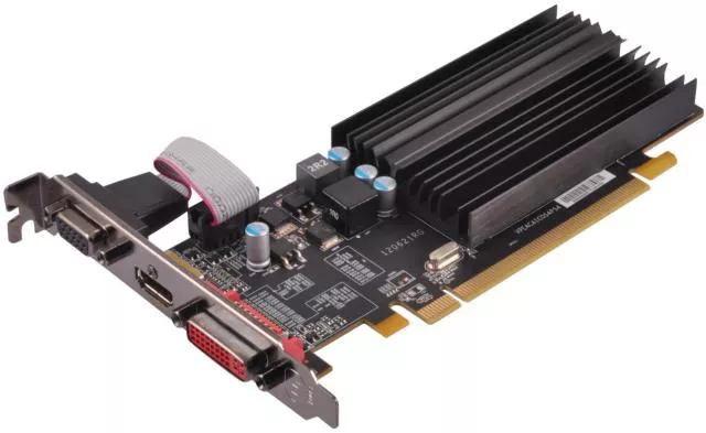
At its simplest, a video card (also called a Graphics Card or GPU) is a specialized piece of hardware responsible for generating and outputing the images you see on your monitor.
While the CPU (Central Processing Unit) is the “brain” of the computer that handles general tasks, the video card is the “artist” that specializes in the complex math required to render 2D and 3D graphics, high-definition video, and complex visual effects.
1. Integrated vs. Discrete Graphics
There are two main ways a computer handles video:
- Integrated Graphics: The graphics processor is built directly into the same chip as the CPU. It shares the system’s RAM (memory) and is designed for everyday tasks like web browsing, office work, and streaming video.
- Discrete Graphics (Video Card): This is a separate, dedicated expansion card with its own processor, its own specialized memory, and its own cooling system. These are required for high-end gaming, video editing, 3D modeling, and AI processing.
2. Key Components of a Video Card
A modern discrete video card is essentially a small computer in itself, consisting of:
- GPU (Graphics Processing Unit): The actual chip that does the heavy lifting. Unlike a CPU, which has a few powerful cores, a GPU has thousands of smaller cores designed to handle many mathematical tasks simultaneously (parallel processing).
- VRAM (Video RAM): Dedicated high-speed memory (like GDDR6) used to store image data, textures, and frame buffers so the GPU can access them instantly.
- VRM (Voltage Regulator Module): Components that convert the power from your power supply into the specific, stable voltages the GPU needs.
- Cooling System: Because they generate a lot of heat, cards use large metal heatsinks and one or more fans (or liquid cooling) to keep temperatures safe.
- Output Ports: Usually a mix of HDMI and DisplayPort to connect to your monitors.
3. How a Video Card Works
When you play a game or watch a video, the process follows a high-speed loop:
- Data Reception: The CPU sends instructions about what should be on the screen.
- Geometry & Lighting: The GPU calculates the position of 3D objects and how light should bounce off them.
- Rasterization: The GPU converts those 3D instructions into a 2D grid of pixels.
- Frame Buffer: The completed image (frame) is stored in the VRAM.
- Output: The card sends that frame through the cable to your monitor at a rate of 60, 144, or even 240 times per second.
4. Main Manufacturers
The video card market is dominated by three major players:
| Manufacturer | Known For | Key Brands |
| NVIDIA | Industry leader, Ray Tracing (RTX), AI/Deep Learning. | GeForce RTX, Quadro |
| AMD | High performance-to-value ratio, open-source friendly. | Radeon RX |
| Intel | Newest entry to discrete cards, strong video encoding. | Arc |
5. Why You Might Need a High-End Card
While integrated graphics are fine for most people, a dedicated video card is essential for:
- Gaming: To achieve high frame rates and realistic visual settings.
- Content Creation: Accelerating video rendering in apps like Premiere Pro or 3D rendering in Blender.
- Multi-Monitor Setups: Running three or more high-resolution displays simultaneously.
- Machine Learning: Using the thousands of GPU cores to train AI models.
How do you troubleshoot configurations?
Troubleshooting configurations requires a methodical approach to separate hardware failures from incorrect settings. Because a single wrong parameter can cause a system-wide failure, IT professionals use a layered strategy to isolate the root cause.
1. The “Divide and Conquer” Method
The most effective way to troubleshoot is to isolate the problem to a specific layer of the IT stack:
- Physical Layer: Is the hardware seated correctly? Are cables secure?
- Firmware Layer: Are the BIOS/UEFI settings correct? Is the firmware version compatible with the hardware?
- Operating System Layer: Are the drivers loaded? Are there resource conflicts (IRQ/DMA)?
- Application Layer: Is the software pointing to the right file paths or database IP?
2. Standard Troubleshooting Steps
When a configuration issue arises, follow this sequence to minimize downtime:
Step A: Identify Recent Changes
Configuration problems rarely happen spontaneously. Ask:
- What was the last thing changed? (Did you update a driver, install a new card, or change a BIOS setting?)
- The “Undo” Rule: Revert the most recent change first to see if the system stabilizes.
Step B: Check Documentation and Baselines
Compare the current “failing” configuration against a Baseline (a record of the settings when the system was working perfectly).
- In BIOS, this often means selecting “Load Setup Defaults” to clear any unstable tweaks.
- In software, this means checking the
.configor.yamlfiles against a template.
Step C: Use Diagnostic Tools
- POST Beep Codes: If the hardware configuration is so broken the screen won’t turn on, listen for beeps from the motherboard.
- Device Manager (Windows): Look for yellow exclamation marks indicating driver or resource conflicts.
- Event Viewer / Logs: Check system logs for specific error codes (e.g., “Timeout connecting to IP 192.168.1.1”).
3. Common Configuration Scenarios
| Scenario | Likely Configuration Culprit | Fix |
| PC won’t boot after RAM upgrade | Incorrect XMP/DOCP profile or voltage. | Clear CMOS to reset to safe speeds. |
| New NIC has no internet | Static IP mismatch or disabled Onboard LAN. | Check BIOS Integrated Peripherals or set to DHCP. |
| USB device not recognized | Power management settings or port disabled. | Disable “USB Selective Suspend” in OS Power Options. |
| Software can’t find database | Wrong Port number or Firewall block. | Verify the .json config file and open the port in Firewall. |
4. Advanced Techniques: The “Silent Killers”
Sometimes the configuration is correct, but the environment prevents it from working:
- Configuration Drift: Over time, manual “quick fixes” accumulate until the system no longer matches its documentation.
- Permissions: A configuration file might have the right settings, but the software doesn’t have the “Read” permission to access that file.
- Firmware Versioning: A hardware configuration might be correct, but the BIOS is too old to recognize the feature (e.g., Resizable BAR on a GPU).
5. The Final Resort: “The Clean Slate”
If you cannot find the specific setting causing the failure:
- Hard Reset: Clear the CMOS (for hardware) or reinstall the application (for software).
- Minimum Functional Configuration: Strip the system down to the bare essentials (one stick of RAM, no extra USB devices, no expansion cards) and add components back one by one until it fails.
How does hardware and software configuration fit within the context of artificial intelligence?
In the context of Artificial Intelligence, configuration shifts from being a “one-time setup” to a continuous, high-performance optimization process. Because AI models require massive computational power and specific data pathways, even minor configuration errors can lead to “bottlenecks” where expensive hardware sits idle.
1. Hardware Configuration: The AI Foundation
AI workloads—especially training Large Language Models (LLMs)—depend on parallel processing. Standard hardware configuration isn’t enough; it must be tuned for high-speed data movement.
- GPU Topology & Interconnects: In a multi-GPU setup (like an NVIDIA DGX station), how the cards are configured to talk to each other is critical. Technologies like NVLink must be configured so GPUs can share memory directly, bypassing the slower PCIe bus.
- VRAM Allocation: Configuring how much Video RAM is reserved for the model versus the “key-value cache” determines how long a conversation or “context window” the AI can handle before it forgets the beginning of the chat.
- Thermal Configuration: AI chips generate extreme heat. Configuration involves setting aggressive “Fan Curves” and thermal throttling limits to ensure the hardware doesn’t slow down (throttle) during a 48-hour training session.
2. Software Configuration: The AI Stack
AI software configuration is rarely about a single app; it’s about managing a “stack” of layers that must all align perfectly.
- CUDA & cuDNN Versions: These are the configuration “translators” for NVIDIA chips. If the version of the CUDA toolkit doesn’t match the version of the AI framework (like PyTorch or TensorFlow), the AI simply won’t run.
- Hyperparameters: These are the “master settings” of the AI itself. Examples include:
- Learning Rate: How fast the AI updates its knowledge.
- Batch Size: How many pieces of data the AI looks at before making an adjustment.
- Quantization: A configuration technique where you “compress” a model (e.g., from 16-bit to 4-bit) so it can fit on consumer-grade hardware like a home PC or a smartphone without losing too much intelligence.
3. The Intersection: AI Orchestration
This is where hardware and software configuration meet. In modern AI “factories,” we use Orchestration to manage thousands of configurations at once.
- Containerization (Docker/Kubernetes): Instead of configuring a physical server, engineers configure a “Container.” This container has the exact OS, drivers, and AI code needed. This allows the same AI to run perfectly on a laptop in Calgary or a massive data center in Tokyo.
- Infrastructure as Code (IaC): Using scripts to automatically configure a cloud server with the right GPUs and software libraries the moment an AI researcher hits “Start.”
4. Edge AI: Configuration for the Real World
When AI moves out of the data center and into “Edge” devices (like smart cameras, drones, or robotics), configuration becomes about efficiency:
- NPU Configuration: Many modern CPUs now include a Neural Processing Unit (NPU). Hardware configuration involves telling the OS to send AI tasks to the NPU to save battery life, rather than using the power-hungry GPU.
- Model Pruning: Configuring the software to “ignore” less important connections in the neural network to speed up response times on mobile devices.
Summary Table: AI Configuration Levels
| Level | Key Parameter | Why it Matters for AI |
| Hardware | PCIe/NVLink Bandwidth | Prevents data “traffic jams” between GPUs. |
| Firmware | Virtualization (VT-x) | Allows AI to run in secure, isolated containers. |
| Software | Library Versions (Triton/CUDA) | Ensures the code can actually “talk” to the chip. |
| Model | Precision (FP16 vs. INT8) | Determines if the AI fits in memory or crashes. |
Solved Problems
Here are 20 high-level technician application problems designed to test diagnostic logic, hardware-software integration, and configuration mastery based on our discussion.
Section 1: Boot & Firmware Diagnostics
1. The “Date with the Past” Problem
- Scenario: A user reports that every morning, their computer shows a “CMOS Checksum Error” and the system time has reset to January 1, 2000.
- Thought Process: The BIOS settings are stored in volatile memory that requires a constant power trickle. If the time resets specifically after the PC has been unplugged or off for a while, the “memory keeper” is failing.
- Solution: Replace the CR2032 CMOS battery on the motherboard and reset the system time/date in the Setup Program.
2. The “Invisible SSD” Upgrade
- Scenario: You install a brand-new NVMe SSD into a 5-year-old motherboard. The drive is physically seated, but the BIOS/UEFI does not list it in the Boot Priority.
- Thought Process: The hardware is newer than the motherboard’s current instructions. The BIOS lacks the microcode to “handshake” with this specific drive technology.
- Solution: Perform a Flash BIOS update using a USB drive to provide the motherboard with the necessary firmware to recognize modern NVMe protocols.
3. The “Locked Gate” Scenario
- Scenario: A technician needs to change the Boot Order to install Linux from a USB, but the BIOS is protected by a Supervisor Password that the previous owner forgot.
- Thought Process: To bypass a firmware-level password, the non-volatile memory must be physically cleared to return all settings to factory defaults.
- Solution: Clear the CMOS by shorting the “CLR_CMOS” motherboard jumpers for 10 seconds or removing the CMOS battery for 5 minutes.
4. The “Ghost in the Machine” Reboot
- Scenario: After a successful BIOS flash, the PC enters a “Boot Loop,” restarting before reaching the Windows logo.
- Thought Process: A BIOS flash resets all settings to defaults. If the OS was originally installed using Legacy/CSM mode but the new BIOS defaulted to UEFI Only, the “handshake” will fail.
- Solution: Enter the UEFI Setup Program and toggle the CSM (Compatibility Support Module) to “Enabled” to match the original OS installation configuration.
Section 2: Hardware & Expansion Configuration
5. The “Sluggish Graphics” Mystery
- Scenario: A user installs a high-end Video Card, but benchmarks show it performing at 50% speed.
- Thought Process: Hardware configuration involves physical placement. Most motherboards only provide full bandwidth (x16) to the top PCIe slot; lower slots often run at x4 or x8.
- Solution: Relocate the Video Card to the primary PCIe x16 slot (usually closest to the CPU) and verify the “Link Speed” in the BIOS.
6. The “Silent Bluetooth” Conflict
- Scenario: You install a PCIe Wi-Fi/Bluetooth combo card. The Wi-Fi works perfectly, but the OS does not detect any Bluetooth hardware.
- Thought Process: Many combo cards use the PCIe bus for Wi-Fi but require a separate data path for Bluetooth.
- Solution: Connect the included 9-pin cable from the NIC to an internal USB 2.0 header on the motherboard to provide the Bluetooth data pathway.
7. The “Hot-Swap” Failure
- Scenario: A technician plugs an external drive into a new eSATA card while the PC is running, but the drive doesn’t appear in Windows until the computer is restarted.
- Thought Process: “Hot-plugging” is a specific logical configuration of the SATA controller. If the controller is set to “IDE” mode or “Hot Plug” is disabled, the OS won’t look for new hardware until boot.
- Solution: Enter the BIOS and ensure the SATA controller is set to AHCI Mode and that “Hot Plug” is enabled for that specific eSATA port.
8. The “USB Power Struggle”
- Scenario: A bus-powered external 2TB hard drive works when plugged into the back of the PC, but “clicks” and fails to mount when plugged into a 4-port unpowered USB hub.
- Thought Process: USB configuration involves power allocation. An unpowered hub divides the 5V/500mA of one port among four, leaving insufficient current for a mechanical drive to spin up.
- Solution: Connect the drive directly to a Root Hub port on the back of the motherboard or use a Powered USB Hub.
Section 3: Network & IT Systems
9. The “IP Address Collision”
- Scenario: A new Network Interface Card (NIC) is installed with a Static IP. The computer has local network access but cannot load any websites (e.g., https://www.google.com/search?q=google.com).
- Thought Process: If local traffic works but domain names don’t resolve, the “translator” is missing.
- Solution: Check the DNS Server configuration parameters in the IPv4 properties and ensure they are pointing to a valid DNS (like 8.8.8.8).
10. The “Unstable Virtual Machine”
- Scenario: A developer tries to launch a Docker container or VirtualBox VM, but receives an error stating “Hardware acceleration is not available.”
- Thought Process: Virtualization is a low-level hardware feature that is often disabled by default in the factory BIOS configuration for security reasons.
- Solution: Enter the BIOS/UEFI and enable Intel VT-x or AMD-V under the “Advanced CPU Configuration” menu.
11. The “Jumbo Frame” Packet Loss
- Scenario: A technician configures a NIC for “Jumbo Frames” (9000 MTU) to speed up video transfers, but the connection becomes highly unstable with constant packet loss.
- Thought Process: Network configuration is an “end-to-end” parameter. If the NIC is sending 9000-byte packets but the switch or router is configured for standard 1500-byte packets, the data is dropped.
- Solution: Either revert the MTU parameter to 1500 or ensure all switches in the network path are configured to support Jumbo Frames.
Section 4: Advanced AI & High-Performance Computing
12. The “AI Memory Crash”
- Scenario: An AI researcher tries to load a 70B parameter model on a 24GB GPU, and the software immediately crashes with an “Out of Memory” (OOM) error.
- Thought Process: This is a software configuration issue regarding model size vs. VRAM capacity.
- Solution: Reconfigure the model using Quantization (e.g., switching from FP16 to INT4 precision) to reduce its memory footprint so it fits within the 24GB limit.
13. The “Bottlenecked Training” Problem
- Scenario: During AI training, the GPU usage is only at 30%, while the CPU is at 100%.
- Thought Process: The “Data Loader” configuration is too slow. The CPU cannot “feed” data to the GPU fast enough.
- Solution: Increase the “Num_Workers” parameter in the AI software configuration to use more CPU threads for data preprocessing.
14. The “Thermal Throttling” Mystery
- Scenario: An AI model performs well for the first 10 minutes, then the processing speed (Tokens per Second) drops by 60% and stays there.
- Thought Process: This is a hardware configuration failure regarding cooling. The GPU is hitting its thermal limit and “throttling” its clock speed to prevent melting.
- Solution: Adjust the Fan Curve configuration in the BIOS or GPU software to be more aggressive, or improve the case’s physical airflow.
Section 5: Systems Integration & Troubleshooting Logic
15. The “Vanishing Configuration”
- Scenario: You change the “Restore on AC Power Loss” setting in BIOS to “Always On,” but after a power flicker, the PC stays off.
- Thought Process: If the BIOS doesn’t “remember” a setting after a power loss, the CMOS battery isn’t doing its job.
- Solution: Replace the CMOS battery and re-verify the setting.
16. The “Driver Rollback” Requirement
- Scenario: After a Windows Update, the Video Card starts showing strange “artifacts” (colored lines) on the screen.
- Thought Process: The new software configuration (driver) is incompatible with the current hardware state or OS version.
- Solution: Use Device Manager to “Roll Back Driver” to the previous stable version.
17. The “POST Code” Silence
- Scenario: A PC won’t turn on. There is no video, but the fans spin. There are no “beeps.”
- Thought Process: Most modern motherboards require a “System Speaker” plugged into the front-panel header to hear beep codes.
- Solution: Install a Motherboard Beeper/Speaker or check for a Diagnostic LED on the board to identify the failing component (CPU, RAM, or VGA).
18. The “Resource Conflict” (Legacy)
- Scenario: You install an old sound card and an old NIC, and now the computer freezes whenever you try to play audio while browsing the web.
- Thought Process: This is likely an IRQ Conflict, where two pieces of hardware are trying to use the same “Interrupt Request” line to talk to the CPU.
- Solution: Manually reassign IRQ addresses in the BIOS/UEFI or move one of the cards to a different PCIe/PCI slot.
19. The “Flash Failure” Recovery
- Scenario: During a BIOS flash, the power goes out. The computer now turns on but has a black screen and won’t POST.
- Thought Process: The BIOS is “bricked”—the firmware is corrupted.
- Solution: Use the BIOS Flashback button and a prepared USB drive (if the motherboard supports it) to force a clean firmware write without needing to reach the BIOS menu.
20. The “RAM Speed” Disappointment
- Scenario: You bought 4000MHz RAM, but Windows Task Manager shows it running at 2133MHz.
- Thought Process: Motherboards default to “safe” JEDEC speeds. The high-speed configuration must be manually toggled.
- Solution: Enter the BIOS and enable the XMP (Intel) or DOCP/EXPO (AMD) profile to automatically apply the correct voltage and timings for the 4000MHz speed.
What is the relationship between information technology hardware and software