
Earth and Atmospheric Sciences
At its core, electromagnetic induction is the process of using magnetic fields to produce an electric current. It occurs when a conductor (like a copper wire) is exposed to a changing magnetic field.
This phenomenon was discovered by Michael Faraday in 1831 and serves as the fundamental principle behind how we generate almost all of our electricity today.
How It Works
For induction to happen, there must be relative motion between a magnetic field and a conductor. This can be achieved in three main ways:
- Moving a magnet into or out of a coil of wire.
- Moving the coil of wire through a stationary magnetic field.
- Changing the strength of the magnetic field (by increasing or decreasing the current in an electromagnet).
Key Scientific Laws
The behavior of induction is governed by two primary rules:
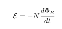
- Faraday’s Law of Induction: This states that the magnitude of the induced electromotive force (EMF) is directly proportional to the rate of change of magnetic flux through the circuit. Mathematically, it is expressed as:
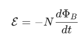
- Where ε is the induced voltage, N is the number of turns in the coil, and dΦB/dt is the rate of change of magnetic flux.
- Lenz’s Law: This explains the direction of the current. It states that the induced current will always flow in a direction that creates a magnetic field opposing the original change in magnetic flux. This is why there is a negative sign in Faraday’s equation—it represents this “nature’s resistance” to change.
Real-World Applications
Electromagnetic induction isn’t just a lab experiment; it’s the backbone of modern technology:
- Electric Generators: These use mechanical energy (from wind, water, or steam) to spin coils of wire inside powerful magnets, converting that motion into the electricity that powers cities.
- Transformers: These devices use induction to step voltage up for long-distance transmission or down for safe use in your home.
- Induction Cooktops: The stovetop creates a rapidly oscillating magnetic field that induces “eddy currents” directly in the metal of the pot, heating the cookware while the stovetop stays relatively cool.
- Wireless Charging: Your smartphone and its charging pad use two induction coils to transfer energy through a magnetic field without needing a direct plug-in connection.
What is the relationship between induced emf and induced current?
The relationship between induced electromotive force (EMF) and induced current is essentially a classic case of cause and effect. While they are closely linked, they represent two different physical properties.
1. Cause vs. Effect
- Induced EMF (ε): This is the “cause.” It is the electrical pressure or potential difference created when a magnetic field changes around a conductor. Think of it like the voltage provided by a battery. Crucially, an EMF can exist even if there is no path for electricity to flow (like an open switch).
- Induced Current (I): This is the “effect.” It is the actual flow of electrons that occurs because of the induced EMF. However, a current can only exist if there is a closed, conducting path (a complete circuit).
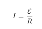
2. The Mathematical Connection (Ohm’s Law)
The two are related by the resistance (R) of the conductor. Just as in a standard DC circuit, they follow Ohm’s Law:
This tells us two important things:
- Proportionality: For a constant resistance, the induced current is directly proportional to the induced EMF. If you move a magnet twice as fast (doubling the EMF), the current will also double.
- Resistance Dependence: Even if you have a massive induced EMF, the resulting current will be tiny if the material has very high resistance. If the circuit is broken (infinite resistance), the current is zero, even though the EMF is still present.
3. Direction and Lenz’s Law
The direction of both the EMF and the current is determined by Lenz’s Law. The induced current creates its own magnetic field that attempts to cancel out the change in the original magnetic field.
If the induced current didn’t oppose the change, it would create an infinite loop of increasing energy, which would violate the Law of Conservation of Energy. Therefore, the work you do to move a magnet near a wire is the source of the energy that becomes the induced EMF and current.
Summary Table
| Feature | Induced EMF (ε) | Induced Current (I) |
| Nature | Potential difference (Voltage) | Flow of charge (Amperage) |
| Requirement | Changing magnetic flux | Changing flux AND a closed circuit |
| Unit | Volts (V) | Amperes (A) |
| Role | The Driving Force | The Resulting Movement |
What is motional emf?
Motional EMF is a specific type of induced electromotive force that occurs when a conductor moves through a stationary magnetic field.
While general electromagnetic induction (Faraday’s Law) often involves a changing magnetic field, motional EMF focuses on the mechanical movement of the conductor itself.
The Mechanism: Magnetic Force on Charges
To understand motional EMF, imagine a straight conducting rod moving at a constant velocity (v) through a uniform magnetic field (B).
- Lorentz Force: Inside the rod, there are free electrons. As the rod moves, these electrons also move through the magnetic field. They experience a magnetic force (FB = qvB).
- Charge Separation: According to the right-hand rule, this force pushes the electrons toward one end of the rod, leaving the other end positively charged.
- Electric Field Creation: This separation of charges creates an internal electric field (E). Eventually, the electric force pulling electrons back (FE = qE) balances the magnetic force pushing them away.
- Steady State: At this point, a stable potential difference—the motional EMF—is established between the two ends of the rod.
The Formula
For a straight conductor of length (L) moving perpendicular to a uniform magnetic field ($B$) at a velocity (v), the magnitude of the motional EMF (ε) is:
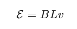
- B: Magnetic field strength (Tesla)
- L: Length of the conductor (Meters)
- v: Velocity of the conductor (Meters per second)
If the rod is part of a closed circuit (for example, sliding along two conducting rails), this EMF will drive a current through the loop.
Energy Conservation
Motional EMF is a perfect demonstration of the Conservation of Energy. To keep the rod moving at a constant velocity while it is in a circuit, you must apply an external force.
- The Work you do by pushing the rod is converted into Electrical Energy (the EMF).
- If you stop pushing, the magnetic “drag” (the force from the induced current) will quickly bring the rod to a halt.
Common Examples
- Airplanes: As an aluminum airplane flies through Earth’s magnetic field, a small motional EMF is generated between its wingtips.
- Tethered Satellites: NASA has experimented with long conducting tethers trailing from shuttles; as they orbit through the Earth’s magnetic field, they generate significant voltage that can power onboard systems.
What is magnetic flux?
To understand electromagnetic induction, magnetic flux (ΦB) is the most important concept to master. It is a measurement of the total magnetic field that passes through a given area.
Think of it like rain falling through a hula hoop:
- The magnetic field is the rain.
- The flux is the total amount of water passing through the hoop’s center.
1. The Mathematical Definition
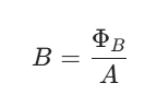
Magnetic flux depends on three factors: the strength of the magnetic field (B), the surface area (A) it passes through, and the angle (θ) at which it hits that surface.
The standard formula is:
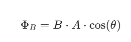
- B: The magnetic field strength (measured in Teslas).
- A: The area of the loop (measured in square meters).
- θ: The angle between the magnetic field and the normal (a line perpendicular to the surface of the loop).
2. Why the Angle Matters
The cos(θ) part of the equation is critical because flux only counts the field lines that actually “pierce” the area:
- Maximum Flux (θ = 0°): When the magnetic field is perfectly perpendicular to the surface, the “hoop” catches every field line possible.
- Zero Flux (θ = 90°): When the field is parallel to the surface, it “skims” across the top and bottom. No lines pass through the area, so the flux is zero.
3. Units of Measurement
The SI unit for magnetic flux is the Weber (Wb).
One Weber is equal to one Tesla-meter squared (T • m2).
In many engineering contexts, you will also hear about Magnetic Flux Density, which is simply another name for the magnetic field (B). It represents the flux per unit area:
4. Its Role in Induction
Magnetic flux is the “trigger” for Faraday’s Law. Importantly, a steady flux does nothing. To generate electricity, you must have a change in flux over time. This happens if:
- The magnetic field (B) gets stronger or weaker.
- The area (A) of the loop changes (e.g., stretching or shrinking the wire).
- The loop rotates, which changes the angle (θ).
What is Faraday’s Law and how does it describe electromagnetic induction?
Faraday’s Law of Induction
Faraday’s Law is the fundamental principle that quantifies how a changing magnetic environment can produce an electromotive force (EMF) in a conductor. While we know that electromagnetic induction is the process, Faraday’s Law provides the specific mathematical rule for how much voltage is generated.
The law states that the induced EMF in a circuit is directly proportional to the time rate of change of the magnetic flux through that circuit.
The Mathematical Equation
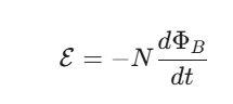
Faraday’s Law is most commonly expressed with the following formula:
- ε (Induced EMF): The voltage generated, measured in Volts.
- N (Number of turns): The number of loops in the wire coil. More loops mean more “surface area” for the magnetic field to interact with, increasing the total EMF.
- dΦB / dt (Rate of change of flux): This is the most critical part. It represents how quickly the magnetic flux is changing.
- The Negative Sign (-): This represents Lenz’s Law, indicating that the induced EMF creates a current that opposes the change in flux.
How It Describes the Process
Faraday’s Law tells us that to get a higher voltage, you don’t necessarily need a “stronger” magnet; you need a faster change. It describes induction through three primary variables:
1. Changing the Magnetic Field (B)
If you move a bar magnet toward a coil, the magnetic field strength inside the coil increases. The faster you move it, the higher the dΦB / dt, and thus the higher the voltage.
2. Changing the Area (A)
If you have a flexible loop of wire in a constant magnetic field and you suddenly squeeze it to make the loop smaller, the magnetic flux decreases because the area decreased. This change in area induces an EMF.
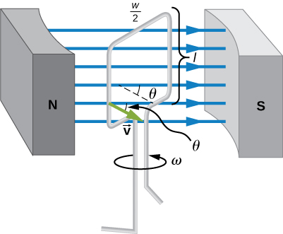
3. Changing the Angle (θ)
This is the principle behind electric generators. By rotating a coil of wire at a constant speed within a magnetic field, the angle between the field lines and the loop is constantly changing. This produces a continuous, oscillating EMF (Alternating Current).
Why It Is Revolutionary
Before Faraday, electricity and magnetism were seen as two separate forces. Faraday’s Law proved they were inextricably linked. It explains:
- How we can turn kinetic energy (spinning a turbine) into electrical energy.
- How energy can be transferred through empty space via fields rather than direct contact.
- The physical basis for the operation of inductors, motors, and transformers.
What is Lenz’s Law?
Lenz’s Law: Nature’s Resistance to Change
Lenz’s Law is a fundamental rule used to determine the direction of an induced electromotive force (EMF) and current. While Faraday’s Law tells us how much voltage is generated, Lenz’s Law tells us which way it flows.
Named after physicist Heinrich Lenz, the law is essentially a statement of the Conservation of Energy.
The Core Principle
Lenz’s Law states that the direction of an induced current is always such that it creates a magnetic field that opposes the change in magnetic flux that produced it.
Think of it as “magnetic inertia.” Nature wants to keep the magnetic flux constant:
- If the magnetic flux through a loop is increasing, the induced current will create a field in the opposite direction to push back.
- If the flux is decreasing, the induced current will create a field in the same direction to try and “propped up” the fading field.
The “Right-Hand Rule” in Action
To find the direction of the current using Lenz’s Law, you follow three steps:
- Identify the Change: Is the external magnetic field through the loop increasing or decreasing?
- Determine the Opposing Field: If the external field is increasing, the induced field must point the opposite way. If it’s decreasing, the induced field points the same way.
- Apply the Right-Hand Rule: Point your right thumb in the direction of the induced magnetic field. your curling fingers will show you the direction the current is flowing.
Why the Negative Sign Matters
In the mathematical expression of Faraday’s Law, Lenz’s Law is represented by the negative sign:
Without this negative sign, the induced current would reinforce the change in flux. This would create a “runaway” effect where the magnetic field and current would grow infinitely large without any extra energy input—which is physically impossible.
Real-World Examples
- Eddy Current Brakes: Used in high-speed trains and roller coasters. When a strong magnet moves past a metal rail, Lenz’s Law creates “eddy currents” that generate a magnetic field opposing the motion, smoothly slowing the vehicle down without physical contact.
- The Copper Pipe Experiment: If you drop a strong neodymium magnet down a plastic pipe, it falls at normal speed. If you drop it down a thick copper pipe, it falls in “slow motion.” This is because the falling magnet induces currents in the copper that create an upward magnetic force, fighting against gravity.
Summary of Directions
| Change in Flux | Induced Magnetic Field Direction |
| Increasing (e.g., magnet moving closer) | Opposite to the external field |
| Decreasing (e.g., magnet moving away) | Same direction as the external field |
How can electromagnetic induction be applied the reproduction of sound?
Electromagnetic induction is the bridge that allows us to convert physical vibrations (sound waves) into electrical signals, and eventually back into sound. This application relies on the relationship between motion, magnets, and coils.
Here are the primary ways this principle is applied in sound technology:
1. Dynamic Microphones (Sound to Electricity)
A dynamic microphone is essentially a miniature electric generator. It uses induction to “capture” sound.
- The Mechanism: A very thin membrane called a diaphragm is attached to a coil of fine wire (the voice coil). This coil is suspended inside the field of a permanent magnet.
- The Process: When sound waves hit the diaphragm, it vibrates back and forth. Because the coil is attached to the diaphragm, it also moves through the magnetic field.
- The Induction: This relative motion creates a changing magnetic flux through the coil, which induces a small alternating current (AC).
- The Result: The frequency and intensity of this electrical current perfectly mimic the original sound waves.
2. Electric Guitar Pickups
Electric guitars do not use microphones; they use pickups which rely entirely on electromagnetic induction to detect string vibrations.
- The Setup: A pickup consists of a permanent magnet wrapped in thousands of turns of copper wire.
- The Interaction: The magnet creates a steady magnetic field that extends up toward the guitar strings. For this to work, the strings must be made of a ferromagnetic material (like steel or nickel).
- The Induction: When a string is plucked, it vibrates within the magnetic field. These vibrations disturb the field, creating a changing magnetic flux through the coil.
- The Result: This induces an electrical signal in the coil that travels to an amplifier.
3. Dynamic Loudspeakers (Electricity back to Sound)
While the “reproduction” of sound usually involves induction to capture it, the output (the speaker) uses the reverse process: the Motor Effect (Lorentz Force).
- The Setup: Like a microphone, a speaker has a voice coil attached to a cone, sitting in a magnetic field.
- The Process: An amplified electrical signal (AC) is sent through the voice coil.
- The Interaction: As the current flows through the coil within the magnetic field, it experiences a magnetic force that pushes the coil (and the attached cone) in and out.
- The Result: The moving cone pushes the air, creating pressure waves that our ears perceive as sound.
4. Magnetic Tape and Phono Cartridges
Though less common in the digital age, analog reproduction relies heavily on induction:
- Phono Cartridges (Vinyl): As the record spins, the needle (stylus) follows the grooves. The movement of the needle moves a tiny magnet near a coil (Moving Magnet) or a tiny coil near a magnet (Moving Coil), inducing the audio signal.
- Tape Heads: Magnetic tape has tiny magnetized particles. As the tape moves past a playback head (a coil wrapped around a core), the changing magnetic fields on the tape induce a current in the coil.
Summary Table: Sound vs. Electricity
| Device | Energy Conversion | Role of Induction |
| Microphone | Kinetic → Electrical | Moving coil induces current from sound waves. |
| Guitar Pickup | Kinetic → Electrical | Vibrating string induces current in the pickup coil. |
| Tape Head | Magnetic → Electrical | Moving magnetic tape induces current in the head coil. |
| Speaker | Electrical → Kinetic | Current in a field creates motion (Reverse Induction/Motor Effect). |
What is an electric generator?
An electric generator is a device that converts mechanical energy into electrical energy. It is the practical application of Faraday’s Law on a massive scale, providing the power used by homes, industries, and entire cities.
How It Works: The Core Mechanism
Most generators operate by rotating a coil of wire within a stationary magnetic field (or rotating a magnet within a stationary coil).
- Mechanical Input: An external force—such as falling water (hydro), blowing wind, or expanding steam from a nuclear or coal plant—spins a shaft.
- Rotation: This shaft is connected to a rotor (either a magnet or a coil of wire). As it spins, the magnetic flux through the wire coils is constantly changing.
- Induction: According to Faraday’s Law, this changing flux induces an electromotive force (EMF), driving an electric current through the circuit.
Essential Components
Every standard generator consists of two main parts:
- The Stator: The stationary part of the generator. In large industrial generators, the stator usually contains the copper windings where the electricity is actually produced.
- The Rotor: The moving part that rotates. In many designs, the rotor is an electromagnet that creates the necessary magnetic field.
- Commutators or Slip Rings: These are electrical contacts that allow the generated current to be transferred from the spinning part of the machine to the external, stationary wires.
Types of Current Produced
1. AC Generators (Alternators)
Most modern generators produce Alternating Current (AC). As the coil rotates $360^{\circ}$, it passes the North pole and then the South pole of the magnet. This causes the induced current to reverse direction twice every full rotation, creating a sine wave pattern.
- Usage: Power grids, car alternators, and backup home generators.
2. DC Generators (Dynamos)
A DC generator uses a special device called a commutator (a split ring). As the coil rotates, the commutator acts as a mechanical switch, reversing the connection to the external circuit every half-turn. This ensures the current always flows in the same direction.
- Usage: Small electronic devices, older automotive systems, and some industrial processes like electroplating.
The Energy Balance
A generator does not “create” energy out of nothing; it is a transducer.
- Input: Mechanical Work (Force * Distance).
- Output: Electrical Energy (Voltage * Current).
Due to Lenz’s Law, the generator actually gets harder to spin the more electrical load you put on it. If you plug in a heavy appliance, the induced current creates a magnetic field that opposes the rotation, requiring the engine or turbine to work harder (consume more fuel or water) to maintain its speed.
What is mutual inductance and what is its relationship to self-inductance?
In electromagnetism, inductance is the property of a conductor that opposes changes in the electric current flowing through it. While both self and mutual inductance rely on Faraday’s Law, they differ in where the energy is stored and how the induction is triggered.
1. Self-Inductance
Self-inductance (L) occurs when a changing current in a circuit induces an electromotive force (EMF) within that same circuit.
- The Mechanism: When current flows through a coil, it creates a magnetic field. If the current changes, the magnetic field also changes. This changing flux “cuts” through the turns of the same coil that created it.
- Back EMF: According to Lenz’s Law, this induced EMF opposes the change in current. This is why it is often called “back EMF.”
- The Formula:
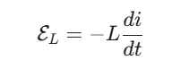
- Where L is the self-inductance of the coil, measured in Henries (H).
2. Mutual Inductance
Mutual inductance (M) occurs when the changing current in one circuit induces an EMF in a second, nearby circuit.
- The Mechanism: Coil 1 (the primary) has a changing current, which creates a changing magnetic field. This field extends through the space to Coil 2 (the secondary). The changing magnetic flux through Coil 2 induces a voltage in it, even though the two coils aren’t physically connected.
- The Formula:
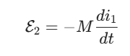
- Where ε2 is the voltage induced in the second coil, and M is the mutual inductance between them.
3. The Relationship Between L and M
The relationship between self and mutual inductance is defined by how well the magnetic fields of the two coils are “coupled.”
The Coupling Coefficient (k)
The maximum possible mutual inductance is limited by the self-inductances of the two individual coils (L1 and L2). The relationship is expressed as:
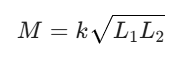
- k (Coupling Coefficient): A value between 0 and 1 that represents the fraction of magnetic flux from one coil that passes through the other.
- k = 1 (Perfect Coupling): All flux lines from Coil 1 pass through Coil 2. This is often achieved by winding both coils around the same iron core.
- k = 0 (No Coupling): The coils are so far apart or poorly oriented that no flux from one reaches the other.
Key Similarities and Differences
| Feature | Self-Inductance (L) | Mutual Inductance (M) |
| Coils Involved | One coil. | Two or more coils. |
| Source of EMF | Change in its own current. | Change in a neighbor’s current. |
| Storage | Stores energy in its own magnetic field. | Transfers energy between circuits. |
| Unit | Henry (H). | Henry (H). |
4. Practical Application: The Transformer
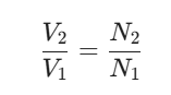
The most famous application of this relationship is the transformer. It uses mutual inductance to change voltage levels. By having different numbers of turns (N) in two perfectly coupled coils (k ≈ 1), we can “step up” or “step down” voltage according to the ratio:
What are transformers?
A transformer is a static electrical device that transfers electrical energy between two or more circuits through electromagnetic induction. Its primary purpose is to change the voltage of alternating current (AC) while maintaining the same frequency.
Transformers are the reason we can efficiently transmit electricity over hundreds of kilometers from power plants to your home.
How a Transformer Works
A transformer has no moving parts. It relies on the principle of mutual inductance between two coils of wire.
- Primary Coil: AC voltage is applied to the first coil. As the current oscillates, it creates a constantly changing magnetic field.
- Magnetic Core: The coils are usually wrapped around a ferromagnetic core (like laminated iron). The core “channels” the changing magnetic flux from the primary coil to the secondary coil.
- Secondary Coil: The changing magnetic flux passes through the second coil. According to Faraday’s Law, this induces a voltage in the secondary coil.
The Transformer Equation
The relationship between the input voltage and output voltage is determined by the turns ratio—the number of loops in the primary coil (Np) versus the secondary coil (Ns).
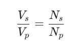
- Step-Up Transformer: If the secondary coil has more turns than the primary (Ns > Np), the output voltage is higher. These are used at power plants to prep electricity for long-distance travel.
- Step-Down Transformer: If the secondary coil has fewer turns (Ns < Np), the output voltage is lower. These are found on utility poles or inside your phone charger to provide safe, usable voltage.
Why Use High Voltage? (The Power of Efficiency)
You might wonder why we bother stepping voltage up to 100,000V or more for transmission. It comes down to Power (P) and Heat (I2R):
- Power is the product of voltage and current (P = V * I).
- To transmit the same amount of power, if you increase the Voltage, you can decrease the Current.
- Since heat loss in wires is proportional to the square of the current, lowering the current drastically reduces energy wasted as heat.
Types of Transformers
- Power Transformers: Large units used in transmission networks for high-voltage transport.
- Distribution Transformers: The “buckets” you see on power poles that step voltage down to 120V or 240V for residential use.
- Isolation Transformers: Used to protect sensitive equipment by physically separating the source from the device while still transferring power.
- Instrument Transformers: Used to safely measure high voltage or current by stepping them down to a level that meters can handle.
Real-World Limitations
In a perfect world, transformers would be 100% efficient. In reality, they lose a small amount of energy through:
- Eddy Currents: Small “whirlpools” of current induced in the iron core that create heat. (This is why cores are made of thin, laminated sheets).
- Hysteresis: The energy required to constantly flip the magnetic domains in the iron core 60 times per second.
- Copper Loss: Heat generated by the resistance of the copper wire itself.