
Earth and Atmospheric Sciences
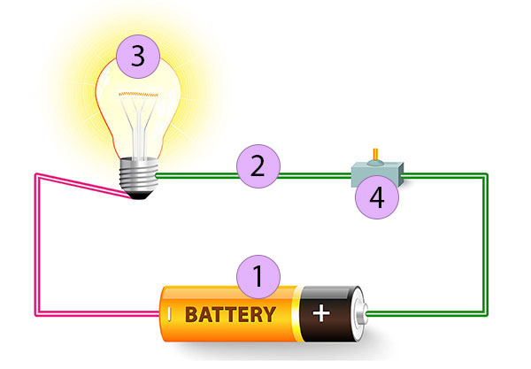
At its simplest, an electric circuit is a closed loop that allows electricity to flow from one point to another. Think of it like a circular racetrack where electrons are the cars; if there’s a gap in the track, the race stops.
To have a functioning circuit, you generally need three core components:
1. The Essential Components
- Energy Source: This provides the “push” (voltage) to get the electrons moving. Common examples include batteries or wall outlets.
- Conductor: The path through which the energy travels, usually copper wires.
- Load: The device that consumes the electricity to do work, such as a lightbulb, a motor, or your phone.
- Switch (Optional but handy): A device used to open or close the circuit, essentially turning the flow on or off.
2. How it Works: Open vs. Closed
Electricity only flows when the path is unbroken.
- Closed Circuit: The path is complete, and the device (the load) is powered on.
- Open Circuit: The path is broken (by a switch or a cut wire), so the flow of electricity stops instantly.
3. Types of Circuit Connections
There are two primary ways to connect multiple components in a circuit:
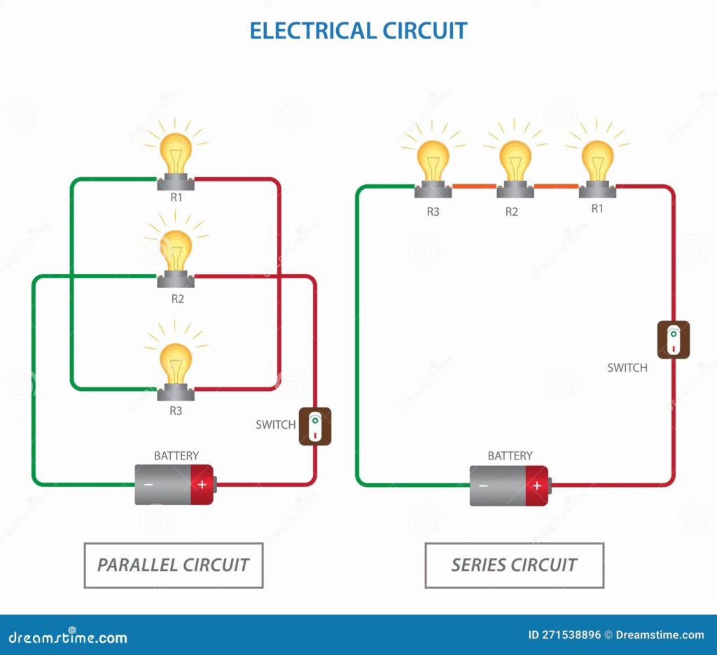
| Type | Description | What happens if one bulb breaks? |
| Series | Components are connected in a single “daisy chain” loop. | The entire circuit breaks; all lights go out. |
| Parallel | Components are connected on separate branches. | Only that branch breaks; the others stay lit. |
4. Key Measurements
In the world of physics and engineering, we describe what’s happening in a circuit using three main variables, linked by Ohm’s Law:
V = I * R
- Voltage (V): The pressure pushing the electrons (measured in Volts).
- Current (I): The actual flow rate of the electrons (measured in Amperes).
- Resistance (R): The “friction” or opposition to the flow (measured in Ohms).
What is the electromotive force and how does it generate current?
Despite the name, Electromotive Force (EMF) isn’t actually a “force” in the Newtonian sense (like a push or a pull). It is better understood as potential energy per unit of charge.+1
Think of EMF as the “pressure” or the “pump” that gives electrons the energy they need to move through a circuit.
1. What exactly is EMF?
EMF is the maximum potential difference that a power source (like a battery or generator) can provide when no current is flowing. It is measured in Volts (V).
- The Battery Analogy: Imagine a water pump in a circular pipe system. The pump creates a pressure difference that forces water to move. EMF is that “pressure” provided by the battery.
- The Energy Source: It represents the work done by the source to move a unit charge from a lower potential to a higher potential.
2. How EMF Generates Current
To get a current (I) flowing, you need two things: a closed loop and a source of EMF. Here is the step-by-step process:
- Energy Conversion: Inside the source, energy (chemical in batteries, mechanical in generators) is converted into electrical energy.
- Charge Separation: This energy creates a buildup of electrons at the negative terminal and a deficit at the positive terminal.
- Potential Difference: This separation creates an Electric Field within the wire.
- Electron Flow: When the circuit is closed, the electric field exerts a force on the free electrons in the conductor, pushing them away from the negative terminal toward the positive terminal. This flow of charge is what we call current.
3. EMF vs. Terminal Voltage
It’s a common point of confusion, but the EMF of a battery is usually higher than the actual voltage you measure when the device is turned on. This is due to Internal Resistance.
V = ϵ – (I * r)
- V (Terminal Voltage): The actual voltage the circuit “sees.”
- ϵ (EMF): The theoretical maximum energy the battery can provide.
- I * r: The energy “lost” as heat inside the battery itself due to its internal resistance (r).
4. How is EMF Created?
There are two main ways we “generate” this electrical pressure:
- Chemical Action: In a battery, chemical reactions move ions to different terminals.
- Electromagnetic Induction: In a generator, moving a wire through a magnetic field (or moving a magnet near a wire) “pushes” the electrons. This is known as Faraday’s Law.
What is Ohm’s law?
Named after the German physicist Georg Simon Ohm, Ohm’s Law is the fundamental rule that describes how electricity behaves in a circuit. It defines the specific relationship between voltage, current, and resistance.
At its core, the law states that the current flowing through a conductor is directly proportional to the voltage applied across it, provided the temperature remains constant.
1. The Mathematical Formula
In any DC (Direct Current) circuit, you can calculate one of the three variables if you know the other two using this equation:
V = I * R
- V (Voltage): The electrical “pressure” or potential difference, measured in Volts (V).
- I (Current): The rate of flow of electrons, measured in Amperes (A).
- R (Resistance): The opposition to that flow, measured in Ohms (ω).
2. The Three Variations
Depending on what you are trying to find, you can rearrange the formula:
- To find Voltage: V = I * R (If you increase current or resistance, you need more voltage to keep the circuit moving.)
- To find Current: I = V / R (If you increase voltage, current goes up; if you increase resistance, current goes down.)
- To find Resistance: R = V / I(This tells you how much a component is fighting the flow of electricity.)
3. A Real-World Analogy: The Garden Hose
To visualize Ohm’s Law, imagine water flowing through a hose:
- Voltage is the water pressure at the faucet. The higher the pressure, the faster the water wants to move.
- Current is the flow rate of the water through the hose.
- Resistance is the size of the hose. A wide hose has low resistance (high flow), while a narrow hose or a kink in the line has high resistance (low flow).
4. Why It Matters
Engineers and hobbyists use Ohm’s Law for almost every electrical task, such as:
- Choosing the right resistor: Ensuring an LED doesn’t blow up by limiting the current flowing through it.
- Safety: Calculating how much current a wire can handle before it overheats and causes a fire.
- Troubleshooting: Determining why a device isn’t getting enough power.
Note: Ohm’s Law applies to “Ohmic” materials (like most metals). Some components, like LEDs or transistors, are “Non-Ohmic,” meaning their resistance changes depending on the voltage applied.
What is the relationship between resistance and resistivity?
While they sound almost identical, the difference between resistance and resistivity is the difference between an object and the material it is made of.
Think of it this way: Resistivity is a property of the “stuff” (like copper or rubber), while Resistance is a property of the specific “thing” (like a 10-meter long thin wire).
1. Defining the Terms
- Resistance (R): This is a measure of how much a specific object opposes the flow of electric current. It depends on the object’s shape, size, and material. It is measured in Ohms (Ω).
- Resistivity (ρ): This is an intrinsic property of a material, regardless of its shape or size. It tells you how strongly a material naturally opposes current. It is measured in Ohm-meters (Ω • m).
2. The Mathematical Relationship
The resistance of a conductor is determined by its resistivity combined with its physical dimensions. The formula is:
R = ρL / A
Where:
- R is the Resistance.
- ρ (rho) is the Resistivity of the material.
- L is the Length of the conductor.
- A is the Cross-sectional Area (thickness).
3. How Changes Affect Resistance
Based on the formula above, you can see how the physical geometry of a wire changes its total resistance:
| Variable | Change | Effect on Resistance (R) | Why? |
| Length (L) | Increase | Increases | Electrons have a longer path to travel and collide with more atoms. |
| Area (A) | Increase | Decreases | A thicker wire provides more “lanes” for electrons to flow through. |
| Resistivity (ρ) | Change Material | Varies | Swapping iron for copper lowers resistance because copper is a better conductor. |
4. Summary of Differences
| Feature | Resistance (R) | Resistivity (ρ) |
| Type of Property | Extrinsic (depends on size/shape). | Intrinsic (depends only on material). |
| Unit | Ohms (Ω). | Ohm-meters (Ω • m). |
| Example | A long wire has more resistance than a short one. | Copper has the same resistivity whether it’s a penny or a mile of cable. |
Pro-Tip: The Temperature Factor
For most metals, both resistance and resistivity increase as temperature rises. This is because the atoms in the material vibrate more violently, making it harder for electrons to “drift” through without crashing into them.
What is electric power?
In the simplest terms, electric power is the rate at which electrical energy is transferred by an electric circuit. If energy is the “work” being done, power is a measure of how fast that work is happening.
In a household context, it’s the difference between a 40-watt lightbulb and a 100-watt lightbulb; the 100-watt bulb consumes energy faster and, as a result, produces more light and heat.
1. The Mathematical Formulas
Electric power is measured in Watts (W), named after James Watt. One Watt is equal to one Joule of energy transferred per second.
The most fundamental formula for power involves voltage and current:
P=V×I
Where:
- P is Power (Watts)
- V is Voltage (Volts)
- I is Current (Amperes)
2. Power and Ohm’s Law
By combining the power formula with Ohm’s Law (V=I×R), we can calculate power even if we don’t know the voltage or the current, as long as we know the Resistance (R):
- If you know Current and Resistance: P=I2×R
- If you know Voltage and Resistance: P=V2 / R
These variations are incredibly useful for engineers. For instance, P=I2×R explains why power lines are high-voltage; by keeping current (I) low, they minimize the power lost as heat in the wires.
3. Power vs. Energy
It is easy to confuse these two, but they are distinct concepts:
| Concept | Definition | Unit | Analogy |
| Power | The rate of using energy. | Watts (W) | The speed of a car. |
| Energy | The total amount of work done. | Joules (J) or Kilowatt-hours (kWh) | The distance the car traveled. |
Your electricity bill is usually charged in Kilowatt-hours (kWh). This measures how many kilowatts of power you used multiplied by the number of hours you used them.
4. Real-World Examples
To give you an idea of the “scale” of power in everyday life:
- LED Nightlight: 1 Watt
- Laptop Charger: 45–100 Watts
- Toaster: 1,000–1,500 Watts
- Electric Clothes Dryer: 3,000–5,000 Watts
- Electric Vehicle Fast Charger: 50,000–350,000 Watts
5. Joule Heating
When current flows through a resistor, the “lost” power isn’t destroyed; it’s converted into heat. This is known as Joule Heating. While this is an “efficiency loss” in a computer processor (which is why you need fans), it is the primary goal of devices like space heaters, hair dryers, and electric stoves.
What is an alternating current?
In most of our previous examples, we talked about electricity flowing like a one-way street (Direct Current or DC). Alternating Current (AC) is different: it is an electric current that periodically reverses its direction and changes its magnitude continuously with time.
Instead of electrons marching in a straight line from a battery’s negative terminal to its positive terminal, they vibrate back and forth—like a saw moving through wood.
1. How AC Works
In an AC system, the voltage switches polarity (positive and negative) at a specific frequency. This creates a wave-like pattern known as a sine wave.
- Frequency: This is how many times the current completes a full “back-and-forth” cycle per second, measured in Hertz (Hz).
- In North America, the standard is 60 Hz (60 times per second).
- In Europe and much of the rest of the world, it is 50 Hz.
2. AC vs. DC: A Quick Comparison
| Feature | Alternating Current (AC) | Direct Current (DC) |
| Direction | Reverses periodically. | Flows in one direction only. |
| Source | Power plants (generators), wall outlets. | Batteries, solar cells, fuel cells. |
| Transmission | Efficient for long distances. | Better for short distances (electronics). |
| Waveform | Usually a Sine wave. | A straight horizontal line. |
3. Why do we use AC for our homes?
You might wonder why we use “vibrating” electricity instead of a steady flow. The answer comes down to transformers and efficiency.
- Voltage Stepping: Using a transformer, AC voltage can easily be “stepped up” to very high levels (like 300,000 Volts) for long-distance travel.
- Lower Energy Loss: At high voltages, the current (I) is very low. Since heat loss in wires is calculated as P = I2 * R, lower current means significantly less energy is wasted as heat during transmission.
- Step Down: Once the electricity reaches your neighborhood, another transformer “steps it down” to a safe level (120V or 230V) for your appliances.
4. How is AC Generated?
AC is typically produced by an alternator (an AC generator). As a coil of wire rotates inside a magnetic field, the changing magnetic flux induces a current that naturally reverses direction as the coil flips over.+1
5. The “Rectifier” Bridge
While our grid runs on AC, most of your modern gadgets (phones, laptops, LED TVs) actually need DC to function. Your charging “brick” or power adapter contains a rectifier—a circuit that converts the incoming AC “vibrations” into a steady DC flow.
What is series wiring?
In an electric circuit, series wiring is a configuration where all components are connected end-to-end, forming a single path for the current to flow. Imagine a group of people holding hands in a circle; if one person lets go, the entire circle is broken.
Because there is only one route, the electricity must pass through every single component in the chain to return to the source.
1. The Key Characteristics
In a series circuit, the electrical variables (Current, Voltage, and Resistance) behave in very specific ways:
- Current is Constant: The same amount of current (I) flows through every component. It has nowhere else to go!
- Voltage is Shared: The total voltage from the source is divided among the components. If you have a 9V battery and three identical bulbs, each bulb “uses” 3V.
- Additive Resistance: The total resistance (Rtotal) is simply the sum of all individual resistances (R1 + R2 + R3…).
2. The “Christmas Light” Effect
The most famous (and often frustrating) example of series wiring is old-fashioned holiday lights.
- The Single Point of Failure: Because there is only one path, if one bulb burns out or is removed, the circuit becomes “open.” The flow of electrons stops instantly, and every light in the strand goes out, even if the other bulbs are perfectly fine.
3. Mathematical Rules of Series Circuits
If you are calculating the values for a series circuit, you use these three fundamental rules:
| Property | Rule | Formula |
| Current | Stays the same throughout. | Itotal = I1 = I2 = I3 |
| Voltage | Divided between components. | Vtotal = V1 + V2 + V3 |
| Resistance | Adds up to a larger total. | Rtotal = R1 + R2 + R3 |
4. Advantages and Disadvantages
Advantages:
- Simple Design: Requires less wiring than parallel circuits.
- Current Control: It’s safer for certain low-power devices because the total resistance increases as you add more components, naturally lowering the current.
- Battery Voltage: Connecting batteries in series (positive to negative) adds their voltages together (e.g., two 1.5V AA batteries in series provide 3V).
Disadvantages:
- Total Failure: One broken component kills the whole circuit.
- Dimming: As you add more loads (like bulbs), the resistance goes up and the available voltage for each load goes down, making bulbs grow dimmer.
5. Common Examples
- Flashlights: Usually have two or three batteries lined up in series to increase voltage.
- Switches and Circuit Breakers: These are always wired in series with the device they protect so they can “cut off” the entire flow of electricity when opened.
- Freezer Thermostats: Wired in series with the cooling element so it can shut the whole system down once the target temperature is reached.
What is parallel wiring?
In contrast to series wiring, parallel wiring is a configuration where components are connected across the same two points, creating multiple paths for the current to flow.
If series wiring is like a single-lane country road, parallel wiring is like a multi-lane highway—if one lane is blocked, traffic can still move through the others.
1. Key Characteristics
In a parallel circuit, electricity behaves differently than in a series circuit:
- Voltage is Constant: Every branch in a parallel circuit receives the full voltage of the source. If you plug a lamp into a 120V outlet, it gets 120V; if you plug in a second lamp, it also gets 120V.+1
- Current is Shared: The total current from the source splits among the branches. Each branch “draws” only the current it needs based on its own resistance.
- Independent Operation: Because each component has its own dedicated path to the power source, turning one off (or having one burn out) does not affect the others.
2. Mathematical Rules of Parallel Circuits
Calculating values for parallel circuits requires a bit more “reciprocal” math than series circuits:
| Property | Rule | Formula |
| Voltage | Stays the same for every branch. | Vtotal = V1 = V2 = V3 |
| Current | Sum of all branch currents. | Itotal = I1 + I2 + I3 |
| Resistance | Decreases as you add branches. | 1 / Rtotal = 1 / R1 + 1 / R2 + 1 / R3 |
Note: Adding more resistors in parallel actually lowers the total resistance of the circuit because you are providing more paths for the electrons to travel.
3. Why Your House Uses Parallel Wiring
Almost every building in the world is wired in parallel. This is for two vital reasons:
- Independence: You can turn off your bedroom light without your refrigerator losing power.
- Consistent Power: Every appliance is designed to run at a specific voltage (e.g., 120V or 230V). Parallel wiring ensures every outlet in your house provides that exact voltage.
4. Advantages and Disadvantages
Advantages:
- Reliability: A failure in one device doesn’t kill the whole system.
- Constant Voltage: All devices perform at their full rated power.
- Scalability: You can add more devices to the circuit easily (up to the limit of the wire’s capacity).
Disadvantages:
- Complexity: Requires significantly more wiring than a series circuit.
- Overload Risk: Since adding more devices lowers total resistance, the total current increases. If you plug too many things into one parallel circuit (like a power strip), the current can become high enough to melt wires or trip a breaker.
5. Summary Comparison
| Feature | Series Wiring | Parallel Wiring |
| Paths | One single path. | Multiple paths. |
| If one bulb blows… | All bulbs go out. | Others stay lit. |
| Voltage | Shared (bulbs get dimmer). | Constant (bulbs stay bright). |
| Total Resistance | Increases as you add loads. | Decreases as you add loads. |
What are circuits wired partially in series and what are circuits wired partially in parallel?
When you combine both series and parallel sections into a single loop, you get what is known as a Series-Parallel Circuit (or a Combination Circuit).
In the real world, almost all complex electronics—from your smartphone to your car’s wiring—use these “hybrid” setups. They allow engineers to control current to specific components while ensuring other parts of the device stay powered independently.
1. How They Are Configured
To understand these, you have to look at how the “groups” of components relate to each other:
Circuits Wired Partially in Series
In this setup, a single component is placed in the “main line” before or after a parallel group.
- The “Master” Component: Anything in the series portion acts as a gatekeeper. If the series component (like a power switch or a fuse) fails, the entire circuit—including the parallel sections—dies.
- Example: A household light switch is in series with the rest of the room’s lights, even though the lights themselves are wired in parallel with each other.
Circuits Wired Partially in Parallel
In this setup, you have “branches” that contain more than one component lined up in a row.
- The “Grouped” Branch: If you have two bulbs in series on one branch of a parallel circuit, and that branch fails, the other branches stay powered. however, if one bulb in that specific branch blows, the other bulb in that same branch goes out too.
- Example: Some older strings of LED lights use this; they consist of several “series” strings connected to each other in “parallel.”
2. How to Analyze a Hybrid Circuit
To calculate the total resistance ($R_{total}$) or current in these circuits, you use a method called Circuit Reduction. You simplify the “blobs” of the circuit one piece at a time:
- Identify Parallel Groups: Find components that share the same two “nodes” (start and end points).
- Calculate their Equivalent Resistance: Use the parallel formula (1 / Req = 1 / R1 + 1 / R2) to treat that whole group as if it were just one single resistor.
- Add the Series Parts: Now that the parallel group is simplified to a single value, just add it to the other series components in the main line.
3. Comparison Table
| Feature | Series-Heavy (Master Switch) | Parallel-Heavy (Branching) |
| Main Goal | Overall control/protection. | Redundancy and shared voltage. |
| Failure Mode | If the series part breaks, everything stops. | If one branch breaks, the rest keep working. |
| Voltage | Dropped across the series part first. | Full voltage reaches the start of the parallel “bank.” |
4. Real-World Application: The Fuse Box
Your home’s electrical panel is the perfect example of a series-parallel circuit:
- Series Component: The Main Breaker. If it trips, your entire house loses power. It is in series with everything.
- Parallel Component: The Individual Circuits (Kitchen, Bedroom, Garage). These are all in parallel with each other. If the kitchen toaster trips the kitchen breaker, your bedroom lights stay on.
What is internal resistance?
In an ideal world, a 12V battery would always provide exactly 12 Volts. In the real world, batteries and generators have a “hidden” obstacle inside them called internal resistance (r).
Internal resistance is the opposition to the flow of current within the voltage source itself. It is caused by the materials the battery is made of—such as the chemicals (electrolytes) and the metal plates—which aren’t perfect conductors.
1. Why it Matters: The Voltage Drop
When you aren’t using a battery, its voltage is at its maximum (the EMF). However, the moment you connect a load and current starts to flow, the battery’s voltage “sags” or drops.
This happens because some of the battery’s energy is used up just trying to push the electrons through its own internal “gunk.” This wasted energy is converted into heat, which is why batteries and phone chargers get warm during use.
2. The Math Behind It
To calculate the actual voltage available to your device (the Terminal Voltage), you subtract the voltage lost inside the battery from the total EMF:
V = ϵ – (I * r)
Where:
- $V$: Terminal Voltage (what your device actually gets).
- ϵ (epsilon): Electromotive Force (the theoretical maximum voltage).
- I: Current flowing through the circuit.
- r: Internal Resistance of the source.
3. Real-World Effects
You can observe internal resistance in action in several common scenarios:
- Dimming Car Headlights: Have you ever noticed your car’s headlights dim for a split second when you start the engine? The starter motor draws a massive amount of current ($I$). Because V = ϵ – Ir, that huge increase in I causes a larger voltage drop inside the battery, leaving less voltage for the headlights.
- Old Batteries: As a battery ages, chemical deposits build up on the internal plates, increasing the internal resistance (r). Eventually, the resistance becomes so high that even if the battery is “charged,” it can’t push enough current to power a device.
- Overheating: If you draw too much current from a source with high internal resistance, the I2r power loss (heat) can cause the battery to swell, leak, or even catch fire.
4. Summary: Ideal vs. Real
| Feature | Ideal Voltage Source | Real Voltage Source |
| Internal Resistance | Zero (0 Ω). | Always greater than zero. |
| Terminal Voltage | Always equals EMF. | Drops as current increases. |
| Efficiency | 100% (No heat lost). | Some energy always lost as heat. |
What are Kirchhoff’s rules?
While Ohm’s Law is great for simple loops, it struggles with complex circuits that have multiple junctions and paths. That is where Kirchhoff’s Rules come in. Developed by Gustav Kirchhoff in 1845, these two laws are the “accountant’s rules” of electronics—they ensure that charge and energy are always conserved.
1. Kirchhoff’s Current Law (KCL)
The Junction Rule
KCL is based on the Conservation of Charge. It states that the total current entering a junction (a point where wires meet) must exactly equal the total current leaving that junction.+1
- The Principle: Electrons can’t just disappear or bunch up at a corner; what goes in must come out.
- The Math: ΣIin = ΣIout
Analogy: Think of a T-junction in a plumbing system. If 5 gallons of water per minute flow into the junction, and 2 gallons go left, exactly 3 gallons must go right.
2. Kirchhoff’s Voltage Law (KVL)
The Loop Rule
KVL is based on the Conservation of Energy. It states that the directed sum of the electrical potential differences (voltages) around any closed loop in a circuit must be zero.
- The Principle: If you start at one point in a circuit and travel in a complete circle back to the start, the “height” you gained from batteries (voltage) must be exactly canceled out by the “height” you lost across resistors.
- The Math: ΣV = 0
3. How to Apply the Rules
To solve a complex circuit using these rules, engineers follow a specific set of steps:
- Label the Junctions: Identify every point where three or more wires meet.
- Assign Current Directions: Draw arrows for the current in each branch (if you guess the direction wrong, your final answer will just be a negative number—no big deal!).
- Apply KCL: Write equations for the junctions.
- Apply KVL: Travel around the loops and write equations for the voltage changes.
- Crossing a battery from – to +? That’s a gain (+V).
- Crossing a resistor in the direction of current? That’s a drop (-IR).
- Solve the System: Use algebra to solve the resulting equations.
4. Why Are They Important?
Without Kirchhoff’s rules, it would be nearly impossible to design:
- Computer Motherboards: Where thousands of paths intersect.
- Power Grids: Where multiple power plants feed into a single network.
- Sensor Arrays: Where tiny changes in current in one branch tell us about the environment.
Summary Table
| Rule | Basis | Focus | Key Equation |
| Current Law (KCL) | Conservation of Charge | Junctions (Points) | ΣI = 0 |
| Voltage Law (KVL) | Conservation of Energy | Loops (Paths) | ΣV = 0 |
How are current, voltage, and resistance measured?
To measure the variables of an electric circuit, we use specific instruments designed to interact with the flow of electrons. While you can buy individual tools for each, most modern hobbyists and professionals use a Multimeter, which combines all three functions into one device.+1
Here is how each is measured and, more importantly, how the tool must be connected to the circuit.
1. Measuring Current (I)
Current is measured using an Ammeter. Because current is the flow of electrons, the meter must be placed directly in the path of that flow.+1
- Unit: Amperes (Amps).
- Connection: In Series. You must actually break the circuit and insert the ammeter so that all the electrons are forced to pass through the meter.
- Safety Note: Ammeters have almost zero internal resistance. If you connect an ammeter in parallel (across a battery), it will cause a short circuit and likely blow a fuse in the meter.
2. Measuring Voltage (V)
Voltage is measured using a Voltmeter. Since voltage is a “potential difference” between two points, you don’t need to break the circuit to measure it.
- Unit: Volts.
- Connection: In Parallel. You simply touch the two probes to the two points you want to measure (e.g., the two sides of a lightbulb or the two terminals of a battery).
- How it works: Voltmeters have very high internal resistance, so they “sniff” the voltage without drawing significant current away from the circuit.
3. Measuring Resistance (R)
Resistance is measured using an Ohmmeter.
- Unit: Ohms (Ω).
- Connection: Component Isolated. You must remove the component from the circuit or turn the power off completely.
- How it works: The ohmmeter sends a tiny, known amount of current from its own internal battery through the component and measures how much the component resists that flow.
- Warning: Never try to measure resistance on a “live” circuit; the external power will likely damage the meter or give a false reading.
4. Summary Table
| Variable | Instrument | Connection Type | Circuit State |
| Current | Ammeter | Series | Powered On |
| Voltage | Voltmeter | Parallel | Powered On |
| Resistance | Ohmmeter | Parallel | Powered Off |
The Modern Tool: The Digital Multimeter (DMM)
A DMM is the “Swiss Army Knife” of electronics. It has a dial that allows you to switch between voltmeter, ammeter, and ohmmeter modes. It also usually includes features to test continuity (a “beep” to show if a wire is broken) and diode health.
How are capacitors wired in series and in parallel?
Capacitors behave as the mathematical “opposites” of resistors. When you wire them together, their total capacitance (the ability to store charge) changes based on how the electric field is distributed across them.
1. Capacitors in Parallel
When capacitors are wired in parallel, they are all connected to the same voltage source. Essentially, you are increasing the total “surface area” available to store electrons.
- The Rule: Total capacitance increases.
- The Formula: You simply add the individual capacitances together. Ctotal = C1 + C2 + C3 + …
- Why? Imagine three small water tanks connected side-by-side. Together, they can hold much more water than any single tank alone. In a circuit, the parallel branches allow more charge (Q) to be stored at the same voltage (V).
2. Capacitors in Series
In a series configuration, the capacitors are connected in a single chain. The charge must be “shared” across the entire line, which actually makes it harder to store charge overall.
- The Rule: Total capacitance decreases. The total will always be smaller than the smallest capacitor in the chain.
- The Formula: You use the reciprocal sum (the same way you calculate parallel resistors). 1 / Ctotal = 1 / C1 + 1 / C2 + 1 / C3 + …
- Why? Wiring them in series effectively increases the distance between the “outer” plates of the first and last capacitor. Since capacitance decreases as the distance between plates increases, the total ability to store energy drops.+1
- Benefit: While you lose capacitance, the voltage rating increases. Two 50V capacitors in series can handle 100V.
3. Summary Comparison
| Feature | Parallel Connection | Series Connection |
| Total Capacitance | Increases (C1 + C2) | Decreases (1 / C1 + 1 / C2) |
| Voltage | Same across all (Vtotal = V1 = V2) | Shared across all (Vtotal = V1 + V2) |
| Charge ($Q$) | Shared (Qtotal = Q1 + Q2) | Same on all (Qtotal = Q1 = Q2) |
| Common Use | Increasing total storage capacity. | Increasing the voltage a circuit can handle. |
4. Pro-Tip: The “Water Tank” Cheat Sheet
If you’re ever confused, just remember:
- Resistors: Series is Easy (Add them), Parallel is Hard (Reciprocals).
- Capacitors: Parallel is Easy (Add them), Series is Hard (Reciprocals).
What are RC circuits?
An RC circuit is a circuit that contains both a Resistor (R) and a Capacitor (C). While simple circuits with just resistors react instantly to changes in voltage, RC circuits introduce the element of time.
Because a capacitor takes time to charge up and time to release its stored energy, these circuits are the fundamental “clocks” and “timers” of the electronics world.
1. How the RC Circuit Works
The behavior of the circuit changes depending on whether the capacitor is charging or discharging.
Charging Phase
When you connect a battery to an RC circuit, the capacitor doesn’t fill up instantly. The resistor “bottlenecks” the flow of electrons.
- At the very start, the capacitor acts like a short circuit (high current).
- As it fills with charge, the voltage across the capacitor (Vc) rises, and the current in the circuit slows down.
- Once the capacitor is fully charged, the current stops completely.
Discharging Phase
If you remove the battery and complete the loop, the capacitor acts like a temporary battery, pushing its stored electrons back through the resistor until its energy is depleted.
2. The Time Constant (τ)
The most important value in an RC circuit is the Time Constant, represented by the Greek letter tau (τ). It tells you exactly how fast the capacitor will charge or discharge.
τ = R * C
- R: Resistance in Ohms (Ω)
- C: Capacitance in Farads (F)
- τ: Time in Seconds (s)
The Rule of Thumb: * It takes one time constant for a capacitor to charge to approximately 63% of its max voltage.
- It is considered “fully charged” (99%) after five time constants (5τ).
3. Real-World Applications
Because they can control the timing of electrical signals, RC circuits are used everywhere:
- Camera Flashes: The circuit slowly charges a capacitor, which then dumps all its energy into the bulb at once when you press the shutter.
- Windshield Wipers: The “intermittent” setting on your wipers is controlled by an RC circuit; changing the resistance (turning the knob) changes how long it takes for the circuit to trigger the next wipe.
- Filtering: They are used to block certain frequencies in audio equipment (like a “bass boost” or “treble cut”).
- Debouncing Switches: When you press a button on a keyboard, it actually “bounces” mechanically. An RC circuit smooths out those tiny spikes so the computer sees only one clean press.
4. Summary Table
| Phase | Voltage across Capacitor (Vc) | Current in Circuit (I) |
| Charging | Starts at zero, rises to max. | Starts at max, drops to zero. |
| Discharging | Starts at max, drops to zero. | Flows in opposite direction, drops to zero. |
| Fully Charged | Equals Source Voltage. | Zero (acts like an open circuit). |
What are the safety requirements and what are the psychological effects of current?
When working with electricity, the “danger” isn’t just a technical problem—it’s a biological one. Our nervous systems are essentially complex electrical networks, which makes us highly susceptible to external current.
Here is the breakdown of how electricity affects the human body and the safety measures designed to prevent it.
1. The Physiological & Psychological Effects of Current
It is a common misconception that “voltage kills.” In reality, current (Amperage) is what does the damage, though high voltage is usually what provides the “push” to get that current through the high resistance of human skin.
| Current (at 60 Hz) | Physical & Psychological Effect |
| 1 mA | Perception Threshold: A light tingle or “static” feeling. |
| 5 mA | Slight Shock: Not painful, but disturbing. Can cause involuntary movement. |
| 6–30 mA | “Let-Go” Threshold: Painful shock. Muscles contract so hard you cannot let go of the wire. |
| 50–150 mA | Respiratory Arrest: Severe pain, localized burning, and the cessation of breathing. |
| 1,000–4,300 mA | Ventricular Fibrillation: The heart’s rhythm is disrupted. Death is likely without immediate medical help. |
| 10,000 mA+ | Cardiac Arrest and Severe Burns: Immediate tissue damage and heart stoppage. |
The Psychological Aspect:
- Startle Response: Even a non-lethal shock can cause a “jump” that leads to secondary injuries, like falling off a ladder or dropping a heavy tool.
- Trauma: Survivors of significant shocks often experience long-term anxiety, “electric phobia,” or PTSD.
- Neurological Impact: Current passing through the brain can cause memory loss, personality changes, or intense confusion.
2. Core Safety Requirements
To mitigate these risks, electrical systems are built with multiple “layers” of protection.
A. Grounding and Bonding
Grounding provides a low-resistance path for electricity to travel into the earth rather than through a person. If a wire comes loose inside a toaster and touches the metal casing, the ground wire carries that “stray” current away safely, usually tripping the breaker in the process.+1
B. GFCI (Ground Fault Circuit Interrupter)
GFCIs are the most important life-saving devices in modern homes, specifically required in “wet” areas like bathrooms and kitchens.
- How it works: It constantly compares the current leaving the “hot” wire to the current returning on the “neutral” wire.
- The Trigger: If there is a tiny difference (as little as 5 mA), the GFCI assumes the missing electricity is leaking through a person and shuts off the power in 1/40th of a second.
C. Overcurrent Protection (Fuses and Breakers)
While GFCIs protect people, fuses and circuit breakers protect property. They sit in series with the circuit and “blow” or trip if the current exceeds the wire’s rating, preventing the wires from getting hot enough to start a fire.
D. Insulation and PPE
- Double Insulation: Many modern tools use plastic casings so that even if a wire fails, there is no metal for the user to touch.
- PPE: Electricians use rubber-soled boots and insulated gloves rated for specific voltages to act as a high-resistance barrier.
3. The “One-Hand” Rule
A classic safety requirement for technicians working on live equipment is the “One-Hand Rule.” By keeping one hand in your pocket, you ensure that if you do receive a shock, the path of the current goes through your hand to your feet, rather than across your chest (hand-to-hand), which would take the current directly through your heart.